READ AND UNDERSTAND THESE INSTRUCTIONS |
|
|
|
| |
INSTRUCTION SHEET NO. |
| ||||
BEFORE INSTALLING LUMINAIRE. |
|
|
|
|
|
| IS:1101FR |
| |||
installation. To prevent electric shock, turn off electricity at main power supply before proceeding. |
|
| |||
This luminaire is intended for installation in accordance with the National Electrical Code and local regulations. |
|
|
|
|
|
To assure full compliance with local codes and regulations, check with your local electrical inspector before |
|
|
|
|
|
Retain these instructions for maintenance reference. |
|
|
|
|
|
|
|
|
|
| |
Page 1 of 1 |
| ||||
| A1106 |
| |||
INSTALLATION PROCEDURE FOR:
Lytecaster® 1101FR and 1001FR Series Remodeler Frame-In Kits
CAUTION: (RISK OF FIRE) THIS IS A
DO NOT INSTALL INSULATION ABOVE OR WITHIN 3 INCHES (76mm) OF ANY PART OF LUMINAIRE.
CAUTION: USE ONLY WITH REFLECTOR TRIMS PROVIDED BY LIGHTOLIER. USE OF OTHER MANUFACTURER’S TRIMS
MAY VOID THE UNDERWRITERS LABORATORIES LISTING AND COULD CONSTITUTE A FIRE HAZARD.
CAUTION: BEFORE INSTALLING
REFLECTOR TO DETERMINE LAMP WATTAGE AND TYPE APPLICABLE FOR YOUR INSTALLATION.
INSTALLATION INSTRUCTIONS
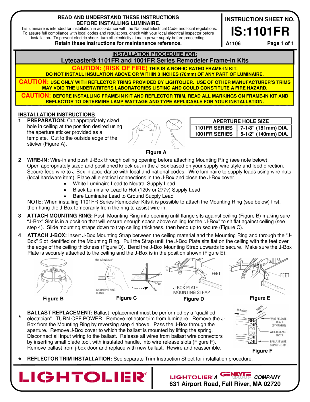
1PREPARATION: Cut appropriately sized hole in ceiling at the position desired using the aperture sticker provided as a template. Cut to the outside edge of the sticker (Figure A).
Figure A
APERTURE HOLE SIZE
1101FR SERIES | |
1001FR SERIES |
|
2
Open appropriately sized and positioned knock out in the
•White Luminaire Lead to Neutral Supply Lead
•Black Luminaire Lead to Hot (120v or 277v) Supply Lead
•Bare Luminaire Lead to Ground Supply Lead
NOTE: When installing 1101FR Series Remodeler Kits it is possible to attach the Mounting Ring (see below) first, then hang the
3ATTACH MOUNTING RING: Push Mounting Ring into opening until flange sits against ceiling (Figure B) making sure
4ATTACH
Figure B | Figure C | Figure D |
BALLAST REPLACEMENT: Ballast replacement must be performed by a “qualified
*electrician”. TURN OFF POWER. Remove reflector trim from luminaire. Remove the J- Box from the Mounting Ring by reversing step 4 above. Pass the
Figure E
Figure F
*REFLECTOR TRIM INSTALLATION: See separate Trim Instruction Sheet for installation procedure.
![]() A
A ![]()
![]()
![]()
![]()
![]()
![]()
![]()
![]()
![]()
![]()
![]()
![]() COMPANY
COMPANY