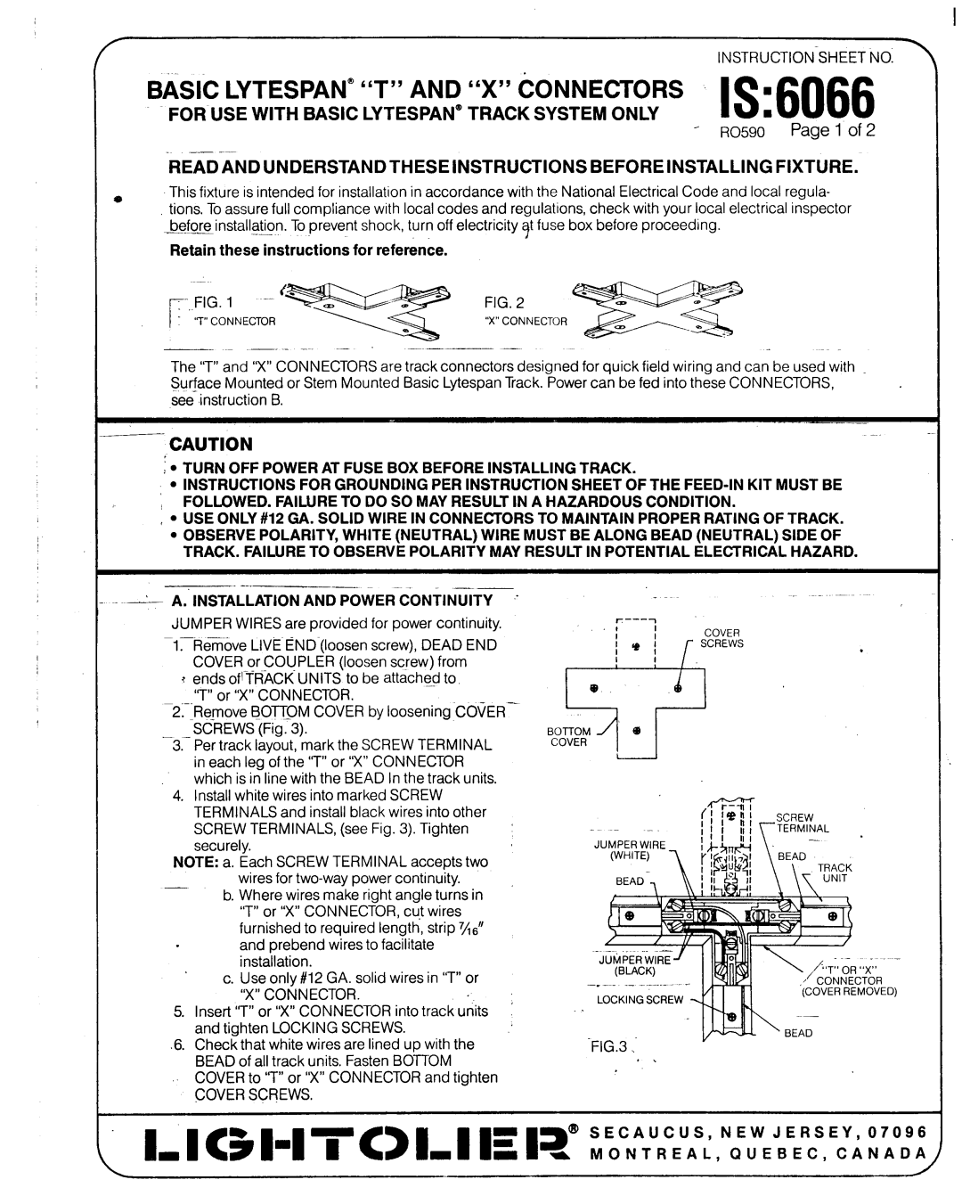
6066 specifications
The Lightolier 6066 is a versatile lighting fixture designed to meet the diverse needs of residential and commercial spaces. This fixture exemplifies a balance of functionality, aesthetic appeal, and energy efficiency, making it an ideal choice for both new construction and retrofitting existing spaces.One of the standout features of the Lightolier 6066 is its sleek and contemporary design. The fixture is available in various finishes, allowing it to complement a wide range of interior decors. Whether placed in a home, office, or retail environment, the 6066 adds a touch of elegance while providing essential illumination.
In terms of technology, the Lightolier 6066 utilizes advanced LED technology, which delivers bright and efficient lighting. LEDs offer significant advantages over traditional incandescent or fluorescent options, including lower energy consumption and a longer lifespan. The integrated LED module in the 6066 ensures that users benefit from reduced electricity bills, minimal maintenance, and enhanced environmental sustainability.
The adjustable features of the Lightolier 6066 further enhance its versatility. It includes tiltable and swiveling options, allowing users to direct light precisely where it is needed. This is especially beneficial in spaces with artwork or architectural features that require focused lighting, giving the user the opportunity to highlight key elements of their environment.
Moreover, the fixture is designed with user-friendly installation in mind. Its compact construction enables easy integration into various ceiling types, whether recessed, surface-mounted, or pendant installations. The straightforward installation process minimizes downtime and disruption, making it a preferred choice for contractors and DIY enthusiasts alike.
Durability is another critical characteristic of the Lightolier 6066. Constructed from high-quality materials, the fixture is built to withstand everyday use without compromising performance. With its excellent thermal management system, the 6066 ensures consistent light output and longevity, making it suitable for high-traffic areas.
In summary, the Lightolier 6066 stands out as a premier lighting solution characterized by its modern design, energy-efficient LED technology, adjustable features, ease of installation, and durability. This fixture not only meets the lighting needs of a space but also enhances the overall aesthetic, proving to be a valuable addition for any lighting project.

