Specifications
9"
1 |
|
| 2 | 3 |
|
|
|
|
|
|
|
|
|
|
|
|
|
3 1/4"
CD7 Direct Louver
0 | 90˚ |
400
800
45˚
1200
0˚ 15˚
Report No. LRL
9"
3 1/4"
67.7% efficiency, 0% ∧ 100% ∨
53.0% efficiency, 0% ∧ 100% ∨
47.5% efficiency, 0% ∧ 100% ∨
All performance data shown are for 2 lamp T8. For other lamping options please refer to spec sheets.
Coefficients of Utilization | Application Data |
|
| ||||||
|
| % Wall Reflectance | Fixture Spacing | Footcandles | Watt /Sq Ft | ||||
|
|
| 50 | 30 | 10 |
|
|
|
|
|
|
| 50’ x 70’ x 8.5’ Space |
|
| ||||
| 0 | 63 | 63 | 63 |
|
|
| ||
|
| 8’ x 8’ (64 sq ft /fixture) | 35 | 1.0 | |||||
Ratio | 1 | 58 | 56 | 55 |
|
|
|
| |
| 8’ x 10’ (80 sq ft /fixture) | 17 | 0.8 | ||||||
2 | 53 | 54 | 49 |
| |||||
|
| ||||||||
|
|
|
|
| |||||
| 3 | 49 | 46 | 44 |
|
|
|
| |
Cavity |
| 12’ x 16’ x 8.5’ Space | 34 | 1.2 | |||||
5 | 41 | 38 | 35 |
| 6’ x 8’ (48 sq ft /fixture) | ||||
| 4 | 45 | 41 | 39 |
|
|
|
| |
Room | 6 | 38 | 34 | 31 |
|
|
|
| |
| 8’ x 8’ x 8.5’ Space |
|
| ||||||
7 | 34 | 31 | 28 |
|
|
| |||
|
| 8’ x 8’ (64 sq ft /fixture) | 19 | 1.0 | |||||
| 8 | 31 | 28 | 25 |
| ||||
| 9 | 29 | 25 | 22 |
| Reflectances: 80% Ceiling, 50% Wall, 20% Floor |
| ||
| 10 | 25 | 21 | 19 |
|
| |||
80% | Ceiling Reflectance |
|
| Light Loss Factor = .75 (.88 BF x 8.5) |
| ||||
|
|
|
|
| |||||
20% | Floor Reflectance |
|
|
|
|
| |||
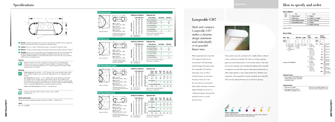
Lowprofile CD7
Sleek and compact, Lowprofile CD7 makes a dynamic
Lighting Systems
How to specify and order
How to Specify
Style |
| Type |
| Lamps |
|
|
|
| |
CD7 | 1 = Direct Louver | 1 | = 1 lamp 4’ | |
|
|
|
|
|
| 2 | = Direct Lens | 2 | = 2 lamp 4’ or 1 lamp 8’ |
|
|
|
|
|
| 3 | = Direct/Indirect Louver | 3 | = 3 lamp 4’ (T8 only) |
|
|
|
|
|
| 4 | = Direct/Indirect Lens | 4 | = 2 lamp 8’ |
|
|
|
|
|
|
|
| 6 | = 3 lamp 8’ (T8 only) |
|
|
|
|
|
Example: CD713
How to Order
Total | Ballast |
4
CD7 Direct Lens
design statement
Style Type | Mounting Length | Lamps | Color | & Voltage |
■1 Housing: Extruded aluminum.
■2 Lamping: One, two or three T8 fluorescent lamps, as specified. Provided by others.
■3 Reflector: Accurate
■4 Shielding: Louver or Lens as specified. Louver:
37 degree shielding lengthwise. Concealed latches operate from either side. Lens: extruded 100% acrylic clear prismatic lens.
Electrical
Specify 120 volt or 277 volt. 3 conductor, 12 gauge wire.
0 | 90˚ |
400
800
1200
45˚
0˚15˚
Report No. LRL
9"
3 1/4"
53.9% efficiency, 0% ∧ 100% ∨
45.7% efficiency, 0% ∧ 100% ∨
49.3% efficiency, 0% ∧ 100% ∨
All performance data shown are for 2 lamp T8. For other lamping options please refer to spec sheets.
Coefficients of Utilization | Application Data |
|
| ||||||
|
| % Wall Reflectance | Fixture Spacing | Footcandles | Watt /Sq Ft | ||||
|
|
| 50 | 30 | 10 |
|
|
|
|
|
|
|
|
|
| ||||
|
|
| 50’ x 70’ x 8.5’ Space |
|
| ||||
| 0 | 54 | 54 | 54 |
|
|
| ||
|
| 8’ x 8’ (64 sq ft /fixture) | 38 | 1.0 | |||||
Ratio | 1 | 49 | 48 | 47 |
|
|
|
| |
| 8’ x 10’ (80 sq ft /fixture) | 18 | 0.8 | ||||||
2 | 45 | 43 | 41 |
| |||||
|
| ||||||||
|
|
|
|
| |||||
| 3 | 42 | 39 | 37 |
|
|
|
| |
Cavity |
| 12’ x 16’ x 8.5’ Space | 36 | 1.2 | |||||
5 | 35 | 32 | 30 |
| 6’ x 8’ (48 sq ft /fixture) | ||||
| 4 | 38 | 35 | 33 |
|
|
|
| |
Room | 6 | 32 | 29 | 27 |
|
|
|
| |
| 8’ x 8’ x 8.5’ Space |
|
| ||||||
7 | 30 | 27 | 24 |
|
|
| |||
|
| 8’ x 8’ (64 sq ft /fixture) | 21 | 1.0 | |||||
| 8 | 27 | 24 | 22 |
| ||||
| 9 | 25 | 22 | 20 |
| Reflectances: 80% Ceiling, 50% Wall, 20% Floor |
| ||
| 10 | 22 | 19 | 17 |
|
| |||
80% | Ceiling Reflectance |
|
| Light Loss Factor = .75 (.88 BF x 8.5) |
| ||||
|
|
|
|
| |||||
20% | Floor Reflectance |
|
|
|
|
| |||
used individually or in graceful linear runs.
When suspended, the Lowprofile CD7 appears to float in the environment. The bold design
These quality materials combined with a highly efficient reflector system, make the Lowprofile CD7 ideal for settings requiring generous overall illumination as well as those where a soft ambi-
CD7 |
|
|
|
|
|
|
|
|
|
|
|
|
|
|
| WH |
|
|
|
|
|
|
|
|
|
|
|
|
|
|
| ||
|
|
|
|
|
|
|
|
|
|
|
|
|
|
|
|
|
1 | = Direct Louver | 1 = Surface | 4 = 4 feet | 1 | = 1 Lamp | White | ||||||||||
2 | = Direct Lens | 2 = Cable | 8 = 8 feet |
| per fixture |
| ||||||||||
3 | = Direct/Indirect | 3 = Stem |
|
|
|
|
| (4' fixture only) |
| |||||||
|
|
|
| Louver | 4 = Wall |
|
|
|
| 2 | = 2 Lamps |
| ||||
4 | = Direct/Indirect |
|
|
|
|
|
|
|
| |||||||
|
|
|
|
|
|
|
| per fixture |
| |||||||
|
|
|
| Lens |
|
|
|
|
|
|
|
|
| |||
|
|
|
|
|
|
|
|
|
|
|
| (2 lamp cross |
| |||
|
|
|
|
|
|
|
|
|
|
|
|
|
|
| ||
|
|
|
|
|
|
|
|
|
|
|
|
|
| section per 4') |
| |
|
|
|
|
|
|
|
|
|
|
|
|
|
| (1 lamp cross |
| |
|
|
|
|
|
|
|
|
|
|
|
|
|
| section per 8') |
| |
|
|
|
|
|
|
|
|
|
|
|
|
| 3 | = 3 Lamps |
| |
|
|
|
|
|
|
|
|
|
|
|
|
|
| per fixture |
| |
|
|
|
|
|
|
|
|
|
|
|
|
|
| (4' fixture only) |
| |
Example: CD71283WHE1 |
|
|
|
| 4 | = 4 Lamps |
| |||||||||
|
|
|
|
| per fixture |
| ||||||||||
Blank = T12 Magnetic 120v
2 = T12 Magnetic
277v
E1 = T12 Electronic
120v
E2 = T12 Electronic
277v
E81 = T8 Electronic
120v
E82 = T8 Electronic
277v
HD1 = T8 PowerSpec HDF Dimming 120v
connectors allow ease of connection for joiner modules. For special circuiting, consult factory. Rapid start, HPF, class “P” thermally protected. PowerSpec® HDF dimming ballast is available.
CD7 Direct/Indirect Louver
and full range of functions make
ence is to be combined with controlled task lighting. The Lowprofile
(2 lamp cross section 8' only)
6 = 6 Lamps per fixture
HD2 = T8 PowerSpec HDF Dimming 277v
M71 = T8 Electronic
Mountings
Cable Suspension (not shown) – 4 1/2" diameter flat canopy finished enamel white, 1/16" diameter stainless steel aircraft cable adjustable up to 36", adjustable cable gripper.
150˚
800
400
0
120˚
90˚
9"
3 1/4"
Coefficients of Utilization | Application Data |
|
|
|
| |||||||
| % Wall Reflectance |
| Ceiling | Susp. | Illum. | Max. | Lum. | W/ | ||||
|
| 50 | 30 | 10 |
|
| Height | Dist. | (FC) | Lum. | Ratio | Sq Ft |
1 | 74 | 72 | 69 |
|
|
|
|
|
|
| ||
|
| 50' x 70' Space |
|
|
|
| ||||||
2 | 66 | 62 | 59 |
|
|
|
|
|
|
|
| |
the Lowprofile CD7 ideal for large open areas as well as contained spaces. Its attractive
is designed to provide both superior photometric performance in either indirect/direct or direct light distributions. Whether stem suspended, cable suspended or surface mounted, the Lowprofile
(3 lamp cross section 8' only)
Individual Fixtures
Dimming Ballast 120v
M72 = T8 Electronic Dimming Ballast 277v
Stem Mounting (not shown) – 4 1/2" diameter flat canopy finished enamel white. 1/2" diameter stem. Chrome plate or white finish. Can be cut to length on job.
Surface and wall mounting (not shown) – consult factory.
Finish
400
800
0˚ | 15˚ | 45˚ |
Report No. LRL
80.3% efficiency, 53.5% ∧ 46.5% ∨
78.9% efficiency, 55.8% ∧ 44.2% ∨
79.9% efficiency, 55.3% ∧ 44.7% ∨
All performance data shown are for
2 lamp T8. For other lamping options please refer to spec sheets.
Room Cavity Ratio | 3 | 59 | 54 | 50 | Luminaire RowSpacing | 10' | 9' | 18' | 72 | 123 | 8.3 | 1.5 | |
4 | 53 | 48 | 43 | 12' | 10.5" | 24" | 60 | 92 | 7.4 | 1.3 | |||
5 | 48 | 42 | 38 |
|
|
|
|
|
|
| |||
| 12’ x 16’ Space |
|
|
|
|
| |||||||
6 | 43 | 37 | 33 |
|
|
|
|
|
| ||||
8' | 9' | 18" | 71 | 119 | 6.9 | 2.0 | |||||||
7 | 39 | 33 | 29 | ||||||||||
8 | 35 | 29 | 25 |
|
|
|
|
|
|
| |||
| 8’ x 8’ x 5’ Cubicle R = 50% |
|
|
| |||||||||
9 | 32 | 26 | 22 |
|
|
|
| ||||||
10 | 28 | 22 | 19 | 12' | 10.5' | 24" | 71 | 90 | 8.6 | 2.0 | |||
80% | Ceiling Reflectance |
|
| Reflectances: 80% Ceiling, 50% Wall, 20% Floor |
|
|
| ||||||
20% | Floor Reflectance |
|
|
|
|
| |||||||
|
| Light Loss Factor = .75 (.88 BF x 8.5) |
|
|
|
| |||||||
|
|
|
|
|
|
|
|
|
| ||||
housing is made up of two
die cast end caps connected by high quality aluminum extrusions. Light shielding is by means of
CD7 provides high performance in an attractive package.
1.Order number of FIXTURES (fixture comes with end caps, mountings and power feeds).
Continuous Rows
1. | Determine run length. | Fixtures can be bolted together and |
2. | Order appropriate number of | through wired to complete long runs. |
| FIXTURES to complete the run. |
|
Powder coated baked white enamel. Custom colors available, consult factory.
Options & Accessories
Fusing, two circuit switching, emergency batteries available – consult factory.
Labels
UL, ULc and IBEW.
CD7 Direct/Indirect Lens
180˚ |
| 150˚ | 120˚ | Coefficients of Utilization |
| Application Data |
|
|
|
| ||||||
800 |
|
| 9" |
|
|
|
|
|
|
|
|
|
|
|
|
|
|
|
|
|
| % Wall Reflectance |
|
| Ceiling | Susp. | Illum. | Max. | Lum. | W/ | |||
|
|
|
|
|
|
|
| |||||||||
400 |
|
| 3 1/4" |
|
| 50 | 30 | 10 |
|
| Height | Dist. | (FC) | Lum. | Ratio | Sq Ft |
0 |
|
| 90˚ | RatioCavity | 0 | 83 | 83 | 83 | SpacingRow |
| 50' x 70' Space |
|
|
|
| |
|
|
| 5 | 48 | 42 | 38 |
| 12’ x 16’ Space |
|
|
|
| ||||
|
|
|
|
| 1 | 73 | 71 | 68 |
| 10' | 9' | 18' | 71 | 123 | 8.4 | 1.5 |
400 |
|
|
| 2 | 66 | 62 | 58 |
| 12' | 10.5" | 24" | 59 | 92 | 7.5 | 1.3 | |
|
|
| 84.1% efficiency, 57.8% ∧ 42.2% ∨ |
| 3 | 59 | 54 | 50 |
| |||||||
800 |
|
|
|
| 4 | 53 | 48 | 43 |
|
|
|
|
|
|
|
|
Report No. LRL | 78% efficiency, 54.6% ∧ 45.4% ∨ | Room | 6 | 43 | 38 | 34 | Luminaire | 8' | 9' | 18" | 70 | 119 | 7.0 | 2.0 | ||
83.6% efficiency, 54.6% ∧ 45.4% ∨ | 9 | 33 | 27 | 24 | 12' | 10.5' | 24" | 70 | 90 | 8.7 | 2.0 | |||||
0˚ | 15˚ | 45˚ |
| 7 | 39 | 34 | 30 |
|
|
|
|
|
|
|
| |
|
|
|
| 8 | 36 | 30 | 26 |
|
| 8’ x 8’ x 5’ Cubicle R = 50% |
|
|
| |||
|
|
|
|
|
|
|
|
|
|
|
|
| ||||
|
|
| All performance data shown are for |
| 10 | 29 | 24 | 20 |
| Reflectances: 80% Ceiling, 50% Wall, 20% Floor |
|
| ||||
|
|
| 2 lamp T8. For other lamping options please | 80% | Ceiling Reflectance |
|
|
|
| |||||||
|
|
| refer to spec sheets. |
|
| Light Loss Factor = .75 (.88 BF x 8.5) |
|
|
|
| ||||||
|
|
| 20% | Floor Reflectance |
|
|
|
|
|
| ||||||
a high performance
ArchitecturalProfiles | Round | Square | Recessed | Cove | Accent | Custom |
Lightolier Lighting Systems
Lightolier Lighting Systems are modular lighting systems that offer a wide selection of geometric shapes, architectural profiles, scales and finishes.