READ AND UNDERSTAND THESE INSTRUCTIONS BEFORE INSTALLING FIXTURE


INSTRUCTION SHEET NO.


This luminaire is intended for installation in accordance with the National Electrical Code and local regulations.


IS:40421


installation. To prevent electric shock, turn off electricity at fuse box before proceeding.


To assure full compliance with local codes and regulations, check with your local electrical inspector before


Retain these instructions for maintenance reference.


C1101


Page 1 of 2


INSTRUCTION SHEET FOR ASSEMBLY AND INSTALLATION

OF 12 & 16” PENDALYTESERIES WITH CORD AND CABLE

Note: This instruction sheet covers several luminaire styles. Powerhead assembly, lamp type, and reflector system may vary slightly from that shown, but installation is the same.

POWER HEAD ASSEMBLY:

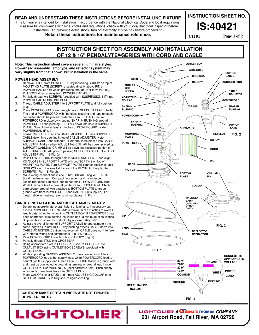
1.Remove DOOR from POWERHEAD by loosening SCREW on top of MOUNTING PLATE (SCREW is located directly above PIN on POWERHEAD DOOR which protrudes through BOTTOM PLATE). Pull DOOR directly away from POWERHEAD (Fig. 1).

2.Partially thread two SCREWS (provided with SUSPENSION KIT) into

POWERHEAD MOUNTING PLATE

3.Thread CABLE ADJUSTER into SUPPORT PLATE and fully tighten (Fig. 2).

4.Place POWERCORD down through hole in SUPPORT PLATE. Note: The end of POWERCORD with fiberglass sleeving and tape on each conductor should be placed inside the POWERHEAD. Secure POWERCORD in place by wrapping SNAP-IN BUSHING around POWERCORD and pushing BUSHING down into hole in SUPPORT PLATE. Note: Allow at least six inches of POWERCORD inside POWERHEAD (Fig. 1).

5.Loosen KNURLED RING on CABLE ADJUSTER. Pass SUPPORT CABLE down into opening in top of CABLE ADJUSTER. Note: SUPPORT CABLE end without CRIMP should be placed into CABLE ADJUSTER. Make certain ADJUSTING COLLAR has been placed up SUPPORT CABLE so CRIMP will go down into recessed portion of ADJUSTING COLLAR prior to passing SUPPORT CABLE into CABLE ADJUSTER (Fig. 1 & Fig. 2).

6.Pass POWERCORD through hole in MOUNTING PLATE and align KEYSLOTS in SUPPORT PLATE with two SCREWS on top of MOUNTING PLATE. Turn SUPPORT PLATE counter-clockwise until SCREWS are in the small slot area of the KEYSLOT. Fully tighten SCREWS. (Fig. 1 & Fig. 2).

7.Make wiring connections inside POWERHEAD using WIRE NUTS (local hardware item). Compact fluorescent and incandescent luminaires: Black luminaire lead to hot (black) POWERCORD lead; White luminaire lead to neutral (white) POWERCORD lead. Attach bare copper ground wire attached to BOTTOM PLATE to green ground wire from POWER CORD and BALLAST (if supplied). For metal halide luminaires, refer to wiring diagram in Fig. 4.

CANOPY INSTALLATION AND HEIGHT ADJUSTMENTS:

1.Determine approximate overall height of luminaire. If necessary cut excess POWERCORD. Note: Add a minimum of six inches to overall length determined for wiring into OUTLET BOX. If POWERCORD has been shortened; strip outside insulation back a minimum of six inches. Strip insulation on each conductor by approximately 3/8”.

2.Adjust the overall length of SUPPORT CABLE to approximately the same length as POWERCORD by pushing excess CABLE down into CABLE ADJUSTER. Caution: make certain CABLE does not interfere with internal wiring and components (Fig. 1 & Fig. 2).

3.Pass POWERCORD through hole in CANOPY (Fig. 1).

4.Partially thread STUD into CROSSBAR.

5.Using appropriate slots in CROSSBAR, secure CROSSBAR to OULTLET BOX using OUTLET BOX SCREWS (provided with

OUTLET BOX).

6.While supporting CANOPY ASSEMBLY make connections: black POWERCORD lead to hot supply lead; white POWERCORD lead to neutral (white) supply lead Green POWERCORD lead is a ground wire and must be connected to grounding terminal or ground lead inside OUTLET BOX. Use WIRE NUTS (local hardware item). Push supply wires and connections back into OUTLET BOX.

7.Place CANOPY over STUD and thread ADJUSTING COLLAR onto STUD until CANOPY is fully secure against ceiling.

CAUTION: MAKE CERTAIN WIRES ARE NOT PINCHED BETWEEN PARTS.


OUTLET BOX


WIRE NUTS

SUPPORT


STUD

CROSSBAR

CABLE

CANOPY

KNURLED RING

OUTLET


BOX


SCREW


CABLE

ADJUSTING


ADJUSTER


COLLAR


POWERCORD

SNAP-IN

CRIMP

SNAP-IN

BUSHING


BUSHING

POWERCORD


SNAP-IN


BUSHING


SUPPORT


APPROX. 6”


PLATE

MOUNTING


KEYSLOT

FIG. 2

PLATE


SCREW


POWER HEAD


DOOR


NECK


PIN


COLLAR

BOTTOM

COLLAR


PLATE

PIN


COLLAR


HALOGEN


LAMP


(AUXILIARY


OPTION


ONLY)


LIP


LENS


FIG. 3


REFLECTOR/


RING

REFRACTOR


FIG. 1


CONNECT TO

277V


APPROPRIATE

BLACK

VOLTAGE

240V


208V


120V

WHITE

POWER

COMMON

CORD


GROUND

GROUND


METAL HALIDE


BALLAST


FIG. 4

A COMPANY

631 Airport Road, Fall River, MA 02720

Page 1
Image 1
Lightolier IS:40421 instruction sheet Power Head Assembly, Canopy Installation and Height Adjustments, Outlet BOX

IS:40421 specifications

Lightolier IS:40421 is a state-of-the-art, sophisticated lighting solution designed to address the ever-evolving needs of both residential and commercial spaces. Renowned for its seamless blend of aesthetics and functionality, this model captures the essence of modern lighting technology.

One of the key features of the Lightolier IS:40421 is its advanced LED technology, which offers significant energy savings compared to traditional lighting options. With a lifespan extending up to 50,000 hours, this fixture not only reduces maintenance costs but also minimizes the frequency of bulb replacements. The efficiency of the LED components contributes to a lower carbon footprint, making it an environmentally friendly choice.

The IS:40421 boasts adjustable color temperatures ranging from warm to cool white, allowing users to select the perfect ambiance for any setting. This feature is particularly beneficial in settings where mood and atmosphere are essential, such as restaurants, galleries, and homes. The ability to customize lighting temperatures empowers users to create diverse environments that can evolve throughout the day.

Moreover, the Lightolier IS:40421 is equipped with dimming capabilities, enabling users to effortlessly adjust brightness levels. This enhances visual comfort and saves energy, aligning with contemporary preferences for versatile lighting solutions. The fixture integrates easily with various control systems, including smart home technologies, adding to its appeal in today's connected environments.

Aesthetically, the IS:40421 is designed with sleek, modern lines that complement any decor style. Its minimalist design ensures that it blends seamlessly into any interior while providing optimal illumination. The option for various finishes further enhances its adaptability, allowing it to serve as both a statement piece and a functional element in any room.

In addition, the construction of the Lightolier IS:40421 is robust and ensures durability, making it suitable for high-traffic areas. Its high-quality materials resist wear and tear over time, sustaining its performance and appearance. This durability combined with efficient heat dissipation ensures that the fixture operates within safe temperature ranges, extending its longevity even further.

In summary, the Lightolier IS:40421 stands out as a versatile and efficient lighting solution. With its advanced LED technology, adjustable color temperatures, dimming features, stylish design, and robust construction, it is an ideal choice for anyone looking to enhance their interior lighting with cutting-edge technology. Whether for home use or commercial application, the IS:40421 redefines what modern lighting can be.