READ AND UNDERSTAND THESE INSTRUCTIONS FULLY.
Failure to follow all instructions can result in damage to the tool, damage to the material and/or serious personal injury. Dust mask,
Always wear eye protection. Use proper safety equipment.
Retain these instructions for future reference.
Clean tool with damp cloth only – do not submerge or place under running water.
INSTRUCTION SHEET NO.
IS: HC356
A0407 |
| Page 1 of 1 |
WARNING: SHOCK HAZARD – DO NOT USE NEAR LIVE ELECTRICAL CIRCUITS.
1WARNING: HEALTH HAZARD – SOME DUST CREATED BY USE OF THIS TOOL AND OTHER CONSTRUCTION
ACTIVITIES, MAY CONTAIN HAZARDOUS MATERIALS SUCH AS LEAD OR ASBESTOS. WORK IN A WELL VENTILATED AREA
AND USE APPROVED SAFETY EQUIPMENT SUCH AS DUST MASKS TO MINIMIZE EXPOSURE TO THESE MATERIALS.
IMPORTANT PRECAUTIONS: Keep your work area clean and well lit. Observe all safety precautions and instructions provided with the power tool with which you use this hole cutter. This tool is designed to be used with a 3/8” chuck or larger drill. Underpowered tools, such as a cordless drill with a partially charged battery, may cause the tool to bind, causing
1ADJUST CUTTING BITS TO DESIRED HOLE SIZE:
Each Lightolier
Hole cutter must be removed from drill before adjusting.
This minimizes the risk of injury due to accidental starting of the drill.
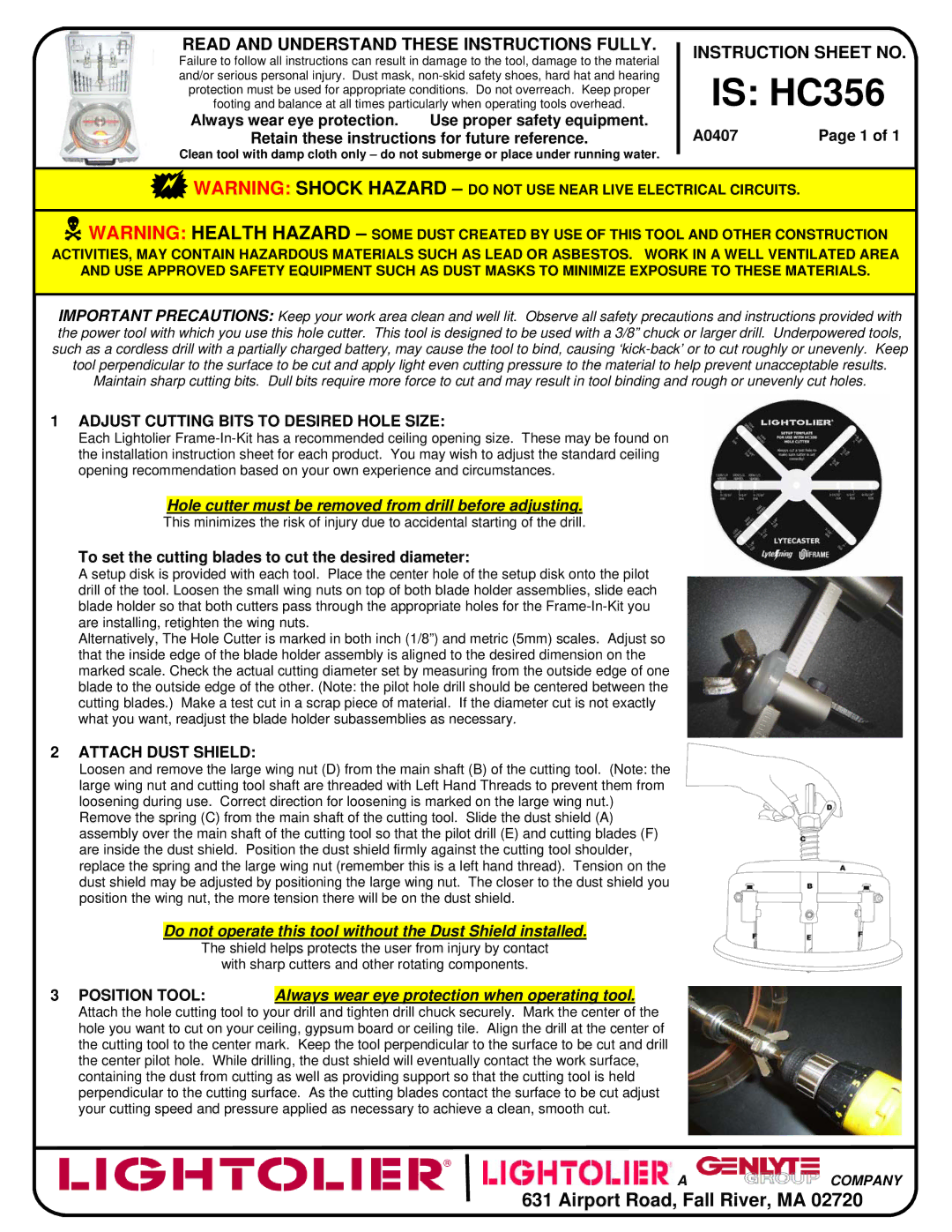
To set the cutting blades to cut the desired diameter:
A setup disk is provided with each tool. Place the center hole of the setup disk onto the pilot drill of the tool. Loosen the small wing nuts on top of both blade holder assemblies, slide each blade holder so that both cutters pass through the appropriate holes for the
Alternatively, The Hole Cutter is marked in both inch (1/8”) and metric (5mm) scales. Adjust so that the inside edge of the blade holder assembly is aligned to the desired dimension on the marked scale. Check the actual cutting diameter set by measuring from the outside edge of one blade to the outside edge of the other. (Note: the pilot hole drill should be centered between the cutting blades.) Make a test cut in a scrap piece of material. If the diameter cut is not exactly what you want, readjust the blade holder subassemblies as necessary.
2ATTACH DUST SHIELD:
Loosen and remove the large wing nut (D) from the main shaft (B) of the cutting tool. (Note: the large wing nut and cutting tool shaft are threaded with Left Hand Threads to prevent them from loosening during use. Correct direction for loosening is marked on the large wing nut.)
Remove the spring (C) from the main shaft of the cutting tool. Slide the dust shield (A) assembly over the main shaft of the cutting tool so that the pilot drill (E) and cutting blades (F) are inside the dust shield. Position the dust shield firmly against the cutting tool shoulder, replace the spring and the large wing nut (remember this is a left hand thread). Tension on the dust shield may be adjusted by positioning the large wing nut. The closer to the dust shield you position the wing nut, the more tension there will be on the dust shield.
Do not operate this tool without the Dust Shield installed.
The shield helps protects the user from injury by contact
with sharp cutters and other rotating components.
3POSITION TOOL: Always wear eye protection when operating tool.
Attach the hole cutting tool to your drill and tighten drill chuck securely. Mark the center of the hole you want to cut on your ceiling, gypsum board or ceiling tile. Align the drill at the center of the cutting tool to the center mark. Keep the tool perpendicular to the surface to be cut and drill the center pilot hole. While drilling, the dust shield will eventually contact the work surface, containing the dust from cutting as well as providing support so that the cutting tool is held perpendicular to the cutting surface. As the cutting blades contact the surface to be cut adjust your cutting speed and pressure applied as necessary to achieve a clean, smooth cut.
![]() A
A ![]()
![]()
![]()
![]()
![]()
![]()
![]()
![]()
![]()
![]()
![]()
![]()
![]()
![]()
![]()
![]()
![]()
![]()
![]() COMPANY
COMPANY
631 Airport Road, Fall River, MA 02720