Low Voltage Transfer Circuit LTC
Page 1 of 1
5.500”
(13.97cm)
For Use with Low Voltage
2.725”
(6.921cm)
1.290”
(3.277cm)
Complete Fixture consists of base unit.
How to Specify:
LTC
Model
Series
LTC = Low Voltage
Transfer Circuit
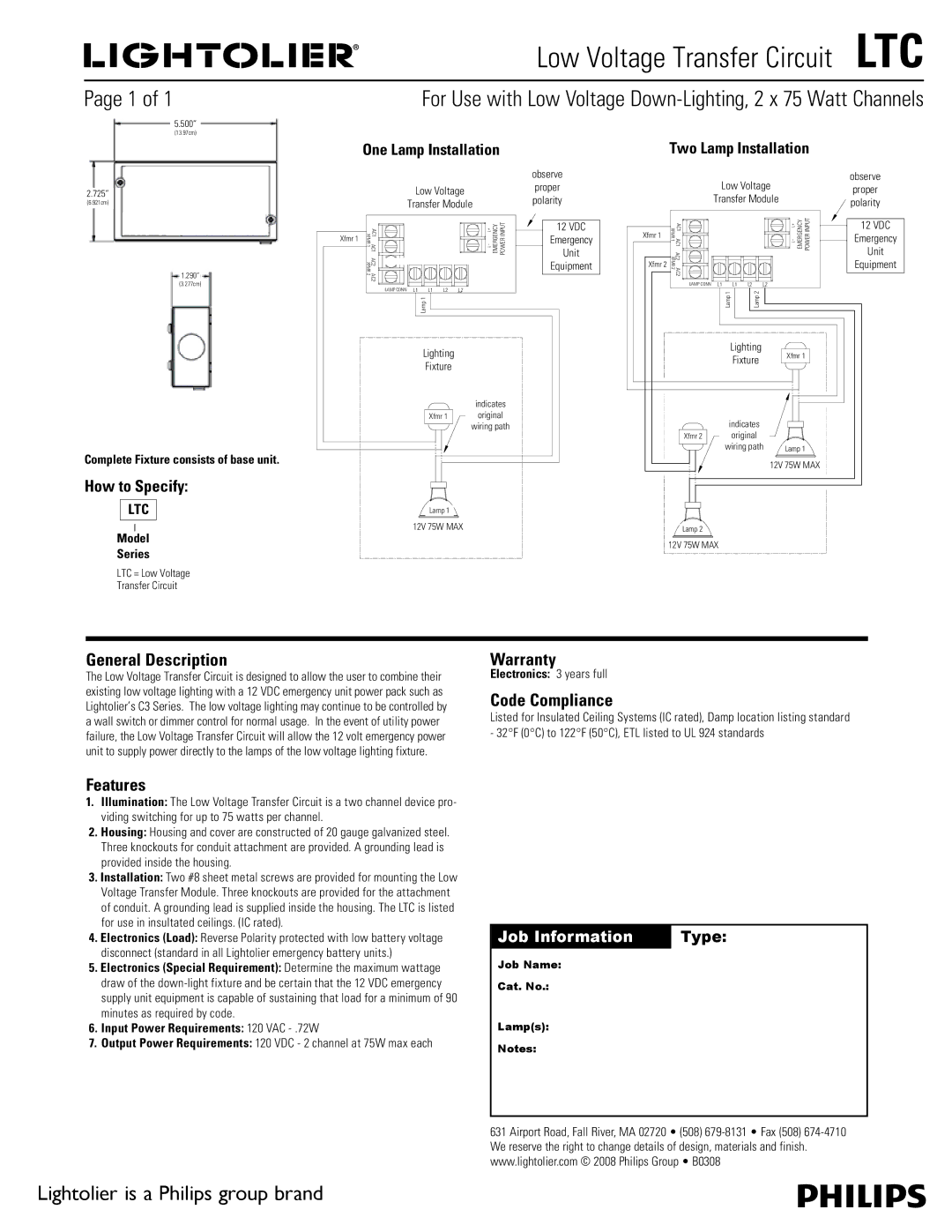
One Lamp Installation
SINGLE LAMP INSTALLATION
|
|
| L+ | observe |
|
| Low Voltage |
| proper |
|
| observe | ||
|
| Transfer Module |
| polarityproper |
|
| Low Voltage |
|
|
|
| Transfer Module |
| polarity |
|
| AC1 XFMR1 | EMERGENCY POWERINPUT | 12 VDC |
|
| Unit | ||
|
| AC1 |
| 12 VDC |
XfmrXfmr1 | 1 |
| Emergency | |
|
| |||
|
|
|
| Unit |
|
| AC2 |
| Equipment |
|
|
| Equipment | |
|
| XFMR |
| |
|
| AC2 2 |
|
|
|
| LAMP CONN L1 L1 L2 L2L2 |
|
|
|
| Lamp11 |
|
|
Lighting
Fixture
indicates
dotted lines
XXfmr 1 indicateoriginalgin l wiringng pathpath
Lamp 1
12V 75WMAX.
Two Lamp Installation
|
| observe | |
Low Voltage | |||
| observ | ||
Low Voltage |
| proper | |
| proper | ||
Transfer Module |
| polarity | |
Transfer Module |
| ||
|
|
|
| AC1 |
|
|
|
| EMERGENCY POWERINPUT | 12 VDC |
Xfmr 1 |
|
|
|
| 12 VDC | ||
AC1 XFMR1 |
|
|
|
| Emergency | ||
Xfmr 1 |
|
|
|
| |||
|
|
|
|
| Unit | ||
| AC2 |
|
|
|
|
| Unit |
|
|
|
|
|
| Equipment | |
Xfmrr 2 | XFMR |
|
|
|
|
| Equipment |
AC2 2 |
|
|
|
|
| ||
|
|
|
|
|
|
| |
| LAMP CONN | L1 | L1 | L2 | L2L2 |
|
|
|
|
| Lamp 1 | Lamp 2 |
|
|
|
|
|
| Lightingg |
| Xfmr 1 |
| |
|
|
|
| e |
|
| |
|
|
| Fixture |
|
|
| |
|
|
| indicates |
|
|
| |
|
|
| dotted lines |
|
|
| |
| Xfmr 2 |
| indicateoriginalgin |
|
|
| |
|
|
|
| g path |
| Lamp11 |
|
|
|
| wiring path |
| |||
|
|
|
|
|
| 12V 75W MAX. |
|
| LLamp22 |
|
|
|
|
|
|
12V75WMAX. |
|
|
|
|
| ||
General Description
The Low Voltage Transfer Circuit is designed to allow the user to combine their existing low voltage lighting with a 12 VDC emergency unit power pack such as Lightolier’s C3 Series. The low voltage lighting may continue to be controlled by a wall switch or dimmer control for normal usage. In the event of utility power failure, the Low Voltage Transfer Circuit will allow the 12 volt emergency power unit to supply power directly to the lamps of the low voltage lighting fixture.
Warranty
Electronics: 3 years full
Code Compliance
Listed for Insulated Ceiling Systems (IC rated), Damp location listing standard - 32°F (0°C) to 122°F (50°C), ETL listed to UL 924 standards
Features
1.Illumination: The Low Voltage Transfer Circuit is a two channel device pro- viding switching for up to 75 watts per channel.
2.Housing: Housing and cover are constructed of 20 gauge galvanized steel. Three knockouts for conduit attachment are provided. A grounding lead is provided inside the housing.
3.Installation: Two #8 sheet metal screws are provided for mounting the Low Voltage Transfer Module. Three knockouts are provided for the attachment of conduit. A grounding lead is supplied inside the housing. The LTC is listed for use in insultated ceilings. (IC rated).
4.Electronics (Load): Reverse Polarity protected with low battery voltage disconnect (standard in all Lightolier emergency battery units.)
5.Electronics (Special Requirement): Determine the maximum wattage draw of the
6.Input Power Requirements: 120 VAC
7.Output Power Requirements: 120 VDC - 2 channel at 75W max each
Job Information | Type: |
|
|
Job Name:
Cat. No.:
Lamp(s):
Notes:
631 Airport Road, Fall River, MA 02720 • (508)
Lightolier is a Philips group brand