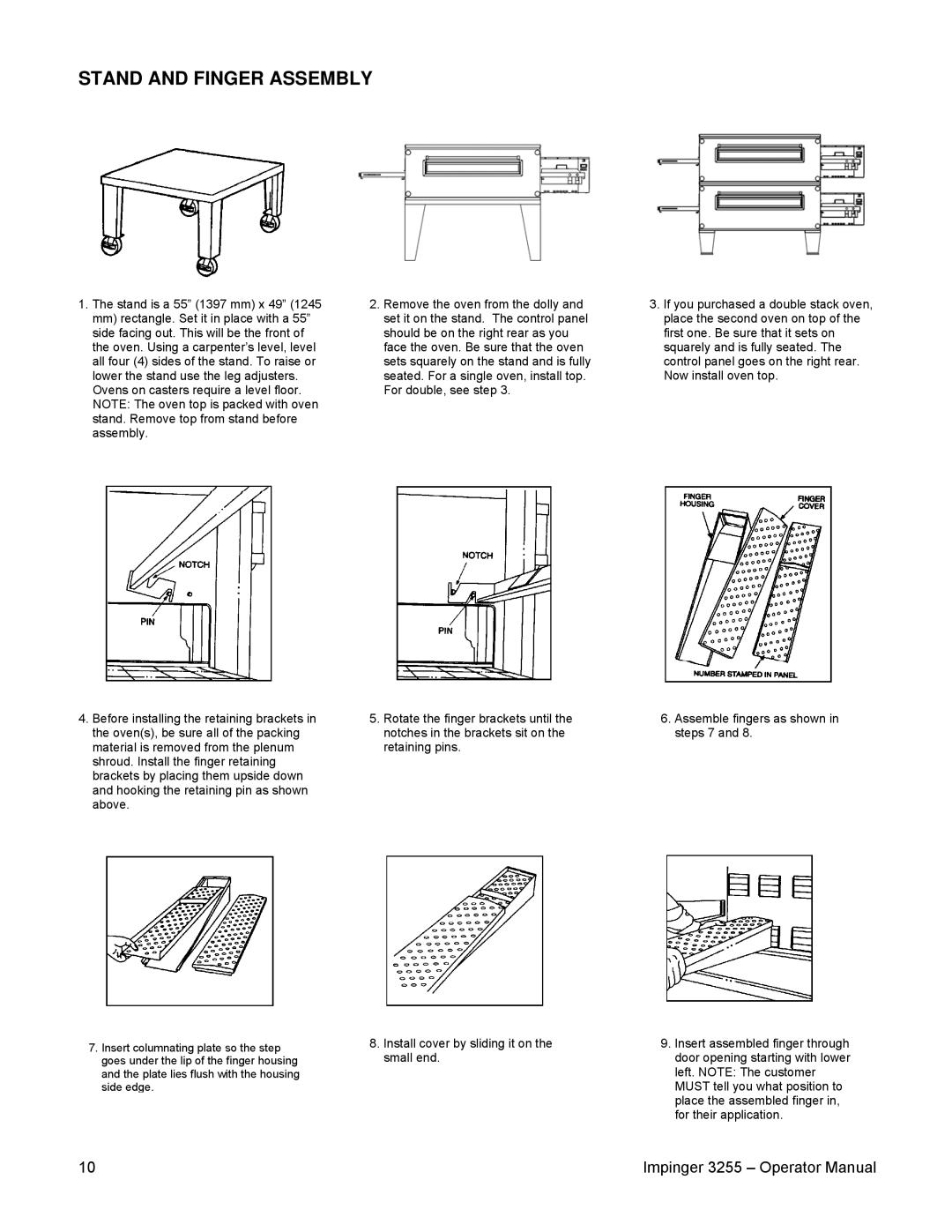
3255 specifications
The Lincoln 3255 is a revolutionary vehicle that has captured the attention of automotive enthusiasts and everyday drivers alike. This luxury sedan embodies a perfect blend of elegance, power, and technology, making it a standout option in the premium vehicle category.At first glance, the Lincoln 3255 presents an eye-catching exterior design. Its aerodynamic silhouette is complemented by a bold front grille and sleek LED headlights, giving it a modern and commanding presence on the road. The elegant lines and contours not only enhance its aesthetics but also improve its overall performance, allowing it to glide effortlessly through various driving conditions.
Under the hood, the Lincoln 3255 is powered by a robust engine lineup that delivers impressive performance. The base model features a turbocharged four-cylinder engine, which provides a perfect balance between power and efficiency. For those seeking more horsepower, an available V6 engine option is offered, delivering exhilarating acceleration and smooth power delivery. Both engine options are paired with an advanced automatic transmission, ensuring a responsive driving experience.
The interior of the Lincoln 3255 is a testament to luxury and comfort. High-quality materials, such as premium leather and authentic wood accents, create an inviting atmosphere. The spacious cabin accommodates both front and rear passengers comfortably, with ample legroom and headroom. The seating is designed with ergonomics in mind, providing support during long journeys.
One of the standout features of the Lincoln 3255 is its state-of-the-art technology suite. The vehicle is equipped with an intuitive infotainment system that includes a large touchscreen display, smartphone integration, and Bluetooth connectivity, allowing users to easily access their favorite apps and music while driving. Advanced driver-assistance systems enhance safety, featuring adaptive cruise control, lane-keeping assist, and automatic emergency braking.
Furthermore, the Lincoln 3255 boasts an impressive sound system that envelops passengers in rich audio, perfect for enjoying music or podcasts. Additionally, its advanced climate control system ensures a comfortable environment, regardless of external weather conditions.
In summary, the Lincoln 3255 is a remarkable luxury sedan that combines striking design, potent performance, and advanced technology. With its commitment to comfort and safety, it is a compelling choice for those seeking a premium driving experience. Whether for daily commutes or weekend getaways, the Lincoln 3255 promises to deliver an unforgettable journey.

