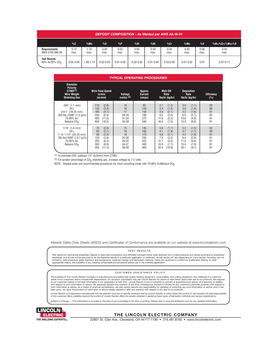
DEPOSIT COMPOSITION - As Welded per AWS A5.18-01
| %C | %Mn | %S | %P | %Si | %Ni | %Cr | %Mo | %V | %Ni+%Cr+%Mo+%V |
|
|
|
|
|
|
|
|
|
|
|
Requirements | 0.12 | 1.75 | 0.03 | 0.03 | 0.90 | 0.50 | 0.20 | 0.30 | 0.08 | 0.50 |
AWS | max. | max. | max. | max. | max. | max. | max. | max. | max. | max. |
|
|
|
|
|
|
|
|
|
|
|
Test Results |
|
|
|
|
|
|
|
|
|
|
80% Ar/20% CO2 | 0.01 |
TYPICAL OPERATING PROCEDURES
Diameter |
|
|
|
|
|
|
|
|
|
|
|
|
Polarity |
|
|
|
|
|
|
|
|
|
|
|
|
CTWD(1) | Wire Feed Speed |
| Approx. | Deposition |
|
| ||||||
Wire Weight |
|
| in/min | Voltage | Current |
| Rate | Rate | Efficiency | |||
Shielding Gas |
|
| (m/min) | (volts) (2) | (amps) | lbs/hr (kg/hr) | lbs/hr (kg/hr) | (%) |
| |||
|
|
|
|
|
|
|
|
|
|
| ||
.045” (1.1 mm) |
| 110 | (2.8) | 15 | 90 | 2.7 | (1.2) | 2.4 | (1.1) | 89 |
| |
DC+ |
| 135 | (3.4) | 16 | 120 | 3.4 | (1.5) | 3.0 | (1.4) | 88 |
| |
| 185 | (4.7) | 17 | 150 | 4.6 | (2.1) | 4.2 | (1.9) | 91 |
| ||
.420 lbs./1000” (7.5 g/m) |
| 250 | (6.4) | 180 | 6.5 | (3.0) | 6.0 | (2.7) | 92 |
| ||
450 | (11.5) | 275 | 11.6 | (5.3) | 10.6 | (4.8) | 91 |
| ||||
Balance CO2 | 650 | (16.5) | 340 | 16.5 | (7.5) | 15.0 | (6.8) | 91 |
| |||
|
|
|
|
|
|
|
|
|
|
|
|
|
1/16” (1.6 mm) |
| 70 | (2.0) | 15 | 145 | 3.6 | (1.7) | 3.3 | (1.5) | 92 |
| |
DC+ |
| 80 | (2.1) | 16 | 160 | 4.1 | (1.9) | 3.7 | (1.7) | 90 |
| |
1” to |
| 90 | (2.3) | 18 | 170 | 4.6 | (2.1) | 4.2 | (1.9) | 91 |
| |
.765 lbs/1000” (13.7 g/m) | 150 | (3.8) | 235 | 7.0 | (3.2) | 6.4 | (2.9) | 91 |
| |||
250 | (6.4) | 325 | 12.1 | (5.5) | 11.0 | (5.0) | 91 |
| ||||
Balance CO2 | 350 | (8.9) | 400 | 16.9 | (7.7) | 15.4 | (7.0) | 91 |
| |||
| 450 | (11.4) | 460 | 22.0 | (10.0) | 20.1 | (9.1) | 91 |
| |||
|
|
|
|
|
|
|
|
|
|
|
|
|
(1)To estimate ESO, subtract 1/4” (6.0mm) from CTWD.
(2)For greater percentage of CO2 shielding gas, increase voltage by
NOTE: Shaded areas are recommended procedures for short circuiting mode with
Material Safety Data Sheets (MSDS) and Certificates of Conformance are available on our website at www.lincolnelectric.com
T E S T R E S U L T S
Test results for mechanical properties, deposit or electrode composition and diffusible hydrogen levels were obtained from a weld produced and tested according to prescribed standards, and should not be assumed to be the expected results in a particular application or weldment. Actual results will vary depending on many factors, including, but not limited to, weld procedure, plate chemistry and temperature, weldment design and fabrication methods. Users are cautioned to confirm by qualification testing, or other appropriate means, the suitability of any welding consumable and procedure before use in the intended application.
C U S T O M E R A S S I S T A N C E P O L I C Y
The business of The Lincoln Electric Company is manufacturing and selling high quality welding equipment, consumables, and cutting equipment. Our challenge is to meet the needs of our customers and to exceed their expectations. On occasion, purchasers may ask Lincoln Electric for advice or information about their use of our products. We respond to our customers based on the best information in our possession at that time. Lincoln Electric is not in a position to warrant or guarantee such advice, and assumes no liability, with respect to such information or advice. We expressly disclaim any warranty of any kind, including any warranty of fitness for any customer’s particular purpose, with respect to such information or advice. As a matter of practical consideration, we also cannot assume any responsibility for updating or correcting any such information or advice once it has been given, nor does the provision of information or advice create, expand or alter any warranty with respect to the sale of our products.
Lincoln Electric is a responsive manufacturer, but the selection and use of specific products sold by Lincoln Electric is solely within the control of, and remains the sole responsibility of the customer. Many variables beyond the control of Lincoln Electric affect the results obtained in applying these types of fabrication methods and service requirements.
Subject to Change — This information is accurate to the best of our knowledge at the time of printing. Please refer to www.lincolnelectric.com for any updated information.
T H E L I N C O L N E L E C T R I C C O M PA N Y
22801 St. Clair Ave., Cleveland, OH