3.Proper placement of the equipment on the under- carriage to ensure stability side to side and front to back when being moved and when standing by itself while being operated or serviced.
4.Typical conditions of use, i.e. travel speed, rough- ness of surface on which the trailer will be operat- ed, environmental conditions & likely maintenance.
5.Conformance with federal, state and local laws. (1)
(1)Consult applicable federal, state and local laws regarding specific requirements for use on public highways.
Polarity Control & Cable Sizes
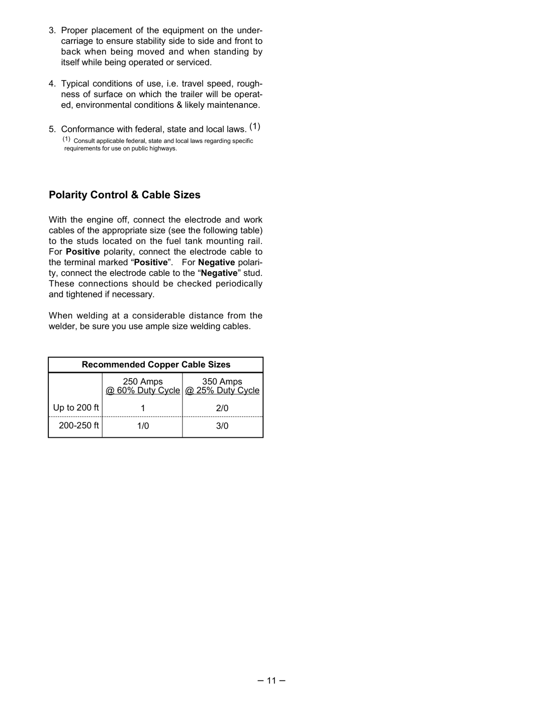
With the engine off, connect the electrode and work cables of the appropriate size (see the following table) to the studs located on the fuel tank mounting rail. For Positive polarity, connect the electrode cable to the terminal marked “Positive”. For Negative polari- ty, connect the electrode cable to the “Negative” stud. These connections should be checked periodically and tightened if necessary.
When welding at a considerable distance from the welder, be sure you use ample size welding cables.
Recommended Copper Cable Sizes
Up to 200 ft
250 Amps | 350 Amps |
@ 60% Duty Cycle | @ 25% Duty Cycle |
1 | 2/0 |
1/0 | 3/0 |
|
|
– 11 –
