English Manual
Mounting
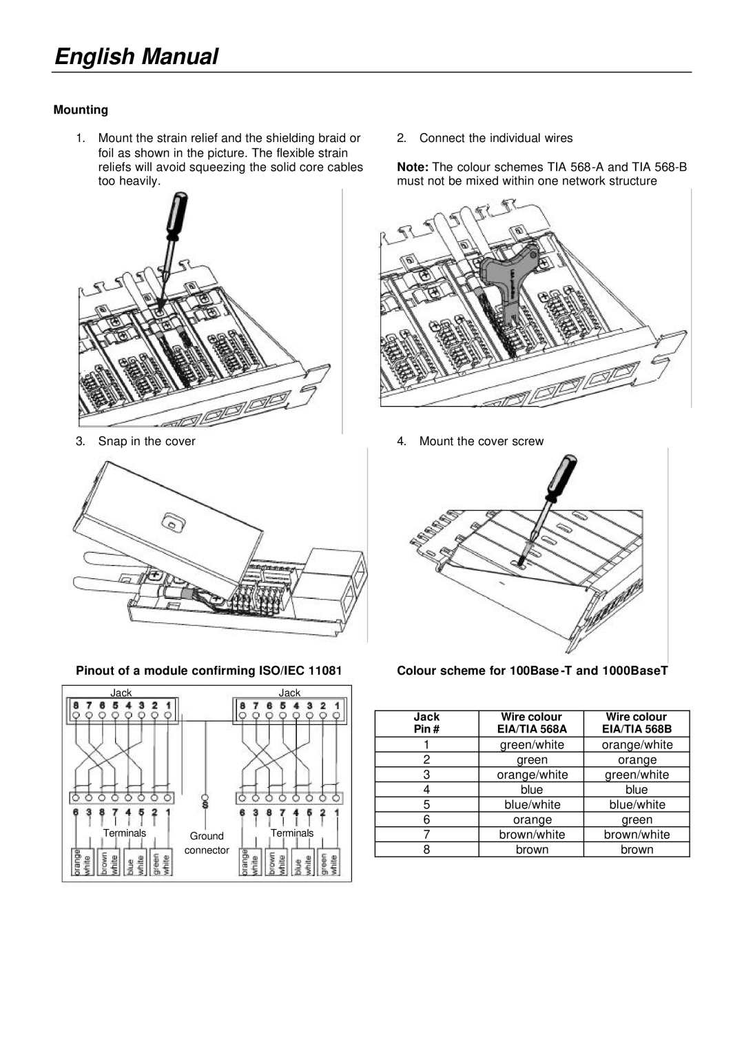
1.Mount the strain relief and the shielding braid or foil as shown in the picture. The flexible strain reliefs will avoid squeezing the solid core cables too heavily.
3.Snap in the cover
2.Connect the individual wires
Note: The colour schemes TIA
4.Mount the cover screw
Pinout of a module confirming ISO/IEC 11081 | Colour scheme for 100Base | ||||
Jack |
| Jack |
|
|
|
|
|
|
|
|
|
|
|
| Jack | Wire colour | Wire colour |
|
|
| Pin # | EIA/TIA 568A | EIA/TIA 568B |
|
|
| 1 | green/white | orange/white |
|
|
| 2 | green | orange |
|
|
| 3 | orange/white | green/white |
|
|
| 4 | blue | blue |
|
|
| 5 | blue/white | blue/white |
|
|
| 6 | orange | green |
Terminals | Ground | Terminals | 7 | brown/white | brown/white |
| connector |
| 8 | brown | brown |
