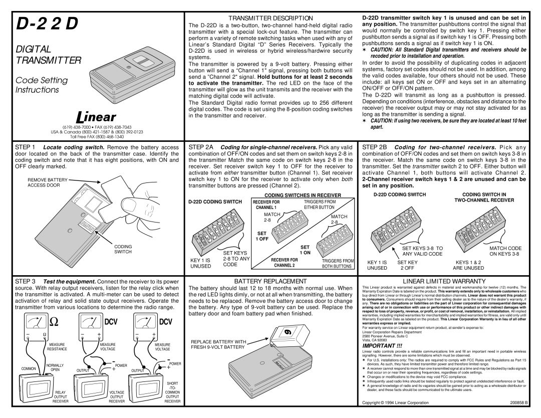
| D-22D | | | | TRANSMITTER DESCRIPTION | D-22D transmitter switch key 1 is unused and can be set in |
| | | The D-22D is a two-button, two-channel hand-held digital radio | any position. The transmitter pushbuttons control the signal that |
| | | transmitter with a special lock-out feature. The transmitter can | would normally be controlled by switch key 1. Pressing either |
| | | | | | perform a variety of remote switching tasks when used with any of | pushbutton sends a signal as if switch key 1 is OFF. Pressing both |
| DIGITAL | | | | Linear’s Standard Digital “D” Series Receivers. Typically the | pushbuttons sends a signal as if switch key 1 is ON. |
| | | | D-22D is used in wireless or hybrid wireless/hardwire security | ✶ CAUTION: All Standard Digital transmitters and receivers should be |
| TRANSMITTER | | | systems. | | | | recoded prior to installation and operation. |
| | | The transmitter is powered by a 9-volt battery. Pressing either | In order to avoid the possibility of duplicating codes in adjacent |
| | | | | | button will send a “Channel 1" signal, pressing both buttons will | systems, factory set codes should not be used. In addition, among |
| Code Setting | | | | send a ”Channel 2" signal. Hold buttons for at least 2 seconds | the valid codes available, four others should not be used. These |
| | | | to activate the transmitter. The red LED on the face of the | include: all keys set ON or OFF and keys set in an alternating |
| Instructions | | | | transmitter will glow as the unit transmits and the receiver with the | ON/OFF or OFF/ON pattern. | |
| | | | | | matching digital code will activate. | | The D-22D will transmit as long as a pushbutton is pressed. |
| | | | | | The Standard Digital radio format provides up to 256 different | Depending on conditions (interference, obstacles and distance to the |
| | | | | | digital codes. The code is set using the 8-position coding switches | receiver) the receiver output may or may not stay activated for as |
| | | | | | in the transmitter and receiver. | | long as the transmitter is sending a signal. |
| | | | | | | | | | ✶ CAUTION: If using two receivers, be sure they are located at least 10 feet |
| | (619) 438-7000 ∙ FAX (619) 438-7043 | | | | | | apart. | | |
| | USA & Canada (800) 421-1587 & (800) 392-0123 | | | | | | | | |
| | | Toll Free FAX (800) 468-1340 | | | | | | | | |
| STEP 1 | Locate coding switch. Remove the battery access | STEP 2A | Coding for single-channel receivers. Pick any valid | STEP 2B | Coding for two-channel receivers. P i ck an y |
| door located on the back of the transmitter case. Identify the | combination of OFF/ON codes and set them on switch keys 2-8 in | combination of OFF/ON codes and set them on switch keys 3-8 in |
| coding switch and note that it has eight positions, with ON and | the transmitter Match the same code on switch keys 2-8 in the | the receiver. Match the same code on switch keys 3-8 in the |
| OFF clearly marked. | | | | receiver. Set receiver switch key 1 to OFF for the receiver to | transmitter. Set the transmitter switch 2 to OFF. Either button will |
| | | | | | activate from either transmitter button (Channel 1). Set receiver | activate Channel 1, both buttons will activate Channel 2. |
| REMOVE BATTERY | | | | switch key 1 to ON for the receiver to activate only when both | 2-Channel receiver switch keys 1 & 2 are unused and can be |
| ACCESS DOOR | | | | transmitter buttons are pressed (Channel 2). | set in any position. | |
| | | | | | | | CODING SWITCHES IN RECEIVER | D-22D CODING SWITCH | CODING SWITCH IN |
| | | | | | D-22D CODING SWITCH | RECEIVER FOR | TRIGGERS FROM | | | TWO-CHANNEL RECEIVER |
| | | | | | | | |
| | | | | | | | CHANNEL 1 | EITHER BUTTON | | | |
| | | | | | | | MATCH | MATCH | | | |
| | | | | | | | 2-8 | | | |
| | | | | | | | 2-8 | | | |
| | | | | | | | | | | |
| | | | | | | | SET | | | | |
| | | | | | | | 1 OFF | | | | |
| | | | CODING | | | | | SET | | SET KEYS 3-8 TO | MATCH CODE |
| | | | SWITCH | | | SET KEYS | | 1 ON | | ANY VALID CODE | ON KEYS 3-8 |
| | | | | | KEY 1 IS | 2-8 TO ANY | RECEIVER FOR | TRIGGERS FROM | KEY 1 IS | SET KEY | KEYS 1 & 2 |
| | | | | | UNUSED | CODE | CHANNEL 2 | BOTH BUTTONS |
| | | | | | UNUSED | 2 OFF | ARE UNUSED |
| | | | | | | | | |
| STEP 3 | Test the equipment. Connect the receiver to its power | | BATTERY REPLACEMENT | | LINEAR LIMITED WARRANTY |
| source. With relay output receivers, listen for the relay click when | The battery should last 12 to 18 months with normal use. When | This Linear product is warranted against defects in material and workmanship for twelve (12) months. The |
| the transmitter is activated. A multi-meter can be used to detect | the red LED lights dimly, or not at all when transmitting, the battery | Warranty Expiration Date is labeled on the product. This warranty extends only to wholesale customers who |
| buy direct from Linear or through Linear’s normal distribution channels. Linear does not warrant this product |
| activation of relay and solid state output receivers. Operate the | needs to be replaced. Remove the battery access door to change | to consumers. Consumers should inquire from their selling dealer as to the nature of the dealer’s warranty, if |
| any. There are no obligations or liabilities on the part of Linear corporation for consequential damages |
| transmitter from various locations to determine the radio range. | the battery. Any type of 9-volt battery can be used. Replace the |
| arising out of or in connection with use or performance of this product or other indirect damages with |
| | | | | | battery door and foam battery pad when finished. | respect to loss of property, revenue, or profit, or cost of removal, installation, or reinstallation. All implied |
| | | | DCV | DCV | warranties, including implied warranties for merchantability and implied warranties for fitness, are valid only until |
| | | | | | | | Warranty Expiration Date as labeled on the product. This Linear Corporation Warranty is in lieu of all other |
| | | | | | | | warranties express or implied. | |
| | | | | | | | | | For warranty service on Linear equipment return product, at sender’s expense to: |
| | | | | | | | | | Linear Corporation Repairs Department | |
| | | | | | | | | | 2580 Pioneer Avenue, Suite C | |
| | | | | | REPLACE BATTERY WITH | | | Vista, CA 92083 | | |
| | MEASURE | | MEASURE | MEASURE | | | IMPORTANT !!! | |
| | | FRESH 9-VOLT BATTERY | | | |
| | RESISTANCE | | VOLTAGE | VOLTAGE | | | |
| | | | | | | Linear radio controls provide a reliable communications link and fill an important need in portable wireless |
| | | | | | | | | |
| | | | | | | | | | signalling. However, there are some limitations which must be observed. |
| | | | | POWER | | | | | ✶ For U.S. installations only: The radios are required to comply with FCC Rules and Regulations as Part 15 |
| | NORMALLY | | POWER | | | | | devices. As such, they have limited transmitter power and therefore limited range. |
| COMMON | | | | | | | ✶ A receiver cannot respond to more than one transmitted signal at a time and may be blocked by radio signals |
| OPEN | OUTPUT | OUTPUT | | | | | |
| | | | | | | that occur on or near their operating frequencies, regardless of code settings. |
| | | | | | | | | |
| | | | | | | | | | ✶ Changes or modifications to the device may void FCC compliance. |
| | | | | SHORT | | | | | ✶ Infrequently used radio links should be tested regularly to protect against undetected interference or fault. |
| | | | | | | | | ✶ A general knowledge of radio and its vagaries should be gained prior to acting as a wholesale distributor or |
| | | | | -TO- | | | | |
| | | | | | | | | dealer, and these facts should be communicated to the ultimate users. |
| | RELAY | | VOLTAGE | COMMON | | | | |
| | | | | | | | | |
| | OUTPUT | | OUTPUT | OUTPUT | | | | | | | |
| | RECEIVER | | RECEIVER | RECEIVER | | | | | Copyright © 1994 Linear Corporation | 200858 B |
| | | | | | | | | |