Linear D-21A(/K) manual Description, Code Switch Location, D-21AN/O TRANSMITTER, Code Setting

Models: D-26A(/K) D-21A(/K) D-24A(/K)

1 2
Download 2 pages 56.73 Kb
Page 1
Image 1
DESCRIPTION

DESCRIPTION

The D-21A(/K), D-24A(/K), and D-26A(/K) are digitally coded stationary radio transmitters triggered by normally open (N/O) or normally closed (N/C) sensors. These transmitters can be programmed to activate any of Linear’s standard digital receivers that are tuned to the same frequency. Each transmitter can perform many remote switching tasks and are typically used in wireless/hardwire security systems. Each unit is powered by a self-contained 9-volt battery and can be connected to various sensors with the built-in screw terminals.

time delay of 1 to 3 seconds, ensuring that the sensor circuit must be continuously open for at least 1 second before the D-24A will transmit. This feature helps prevent activation from short-term, spurious signals, and from signals made from outside electromagnetic sources. The transmitter may be re-triggered after a 30-second reset time. The transmitter has a pushbutton for battery/transmission test.

NOTE: On the D-24A, the loop input terminals must be closed for a minimum of 45 seconds before the pushbutton will activate the transmitter.

CODE SWITCH LOCATION

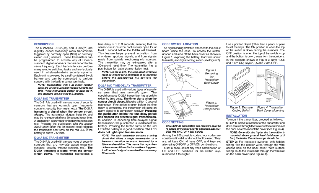
The digital coding switch is attached to the circuit board inside the case. To access the switch, unsnap and slide off the back cover as shown in Figure 1, exposing the battery, lead wire screw terminals, and digital coding switch (see Figure 2).

Figure 1.

Removing

the

Transmitter

Back Cover

Use a pointed object (other than a pencil or pen) to set the keys. The ON position is when the top of the switch is down, facing the numbers. The OFF position is when the top of the switch is up and the bottom is down, away from the numbers. In the example shown in Figure 3, keys 1,4,6 and 8 are ON; keys 2,3,5 and 7 are OFF.

MOUNTING

SCREWS

8

7

NOTE: Transmitters with a /K model number suffix are Linear’s Canadian models tuned to 318 MHz. These instructions pertain to both the /K and standard 303.875 MHz U.S. models.

D-21A N/O TRANSMITTER

The D-21A is used with various types of security sensors that are normally open (magnetic contacts, security floor mats, etc.). The D-21A transmits a signal when the sensor circuit closes. The transmitter triggers instantly, and may be re-triggered after a 30-second reset time. A pushbutton is provided for battery/transmission test. Pressing the pushbutton with the sensor

D-26A N/O TIME-DELAY TRANSMITTER

The D-26A is used with various types of security sensors that are normally open. The special-purpose D-26A transmitter has a built-in exit/entry time delay. The timer starts when the sensor circuit closes. It begins a 5 to 10 second countdown. If no action is taken before the time delay is completed, the transmitter will send an alarm signal to its companion receiver. Pressing the pushbutton before the time delay period has elapsed will prevent signal transmission. In addition to canceling time-delayed signal transmission, the pushbutton is used to test the

CODING

SWITCH

9-VOLT BATTERY

SCREW

TERMINALS

CODE SETTING

Figure 2.

Transmitter

Components


6


5


4


3


2


1

RECESSED

O


N

WIRING


OF

HOLE


F


SURFACE


WIRING


SLOT

Figure 3. Example

Figure 4. Transmitter

Coding Switch

Back Cover Mounting

INSTALLATION

To mount the transmitter, proceed as follows: STEP 1: Select a location for the transmitter and

circuit open (after the 30-second reset) triggers the transmitter and turns on the red LED if the battery is above 7.5 volts.

D-24A N/C TRANSMITTER

The D-24A is used with various types of security sensors that are normally closed (magnetic contacts, security window screens, etc.). The

D-24A transmits a signal when the sensor circuit opens. The transmitter incorporates a

battery. Pressing the button turns on the red LED if the battery is in good condition. The LED

does not light upon transmission.

NOTE: The each transmitter contains a timing circuit that allows a single transmission of a 2-second duration to occur, followed by a 30-second reset time. This means that regardless of the number of times the transmitter is triggered, it will not send a signal more often than once every 30 seconds.

CAUTION! All transmitters and receivers must be re-coded by installer prior to operation. DO NOT USE THE FACTORY SET CODE!

Among the 256 possible codes, four codes are considered invalid, and should not be used. They are: all keys ON, all keys OFF, and keys set alternating ON/OFF or OFF/ON combinations.

To set a code, select any valid combination of ON and OFF positions for the switch keys numbered 1 through 8.

drive screws through the two countersunk holes of the back cover to mount the cover (see Figure 4).

NOTE: Generally, the higher the transmitter is mounted above ground level (minimum of 3 feet) the better the radio range should be.

STEP 2: For recessed switches with hidden wiring, fish the sensor wires through the wire access hole on the back cover. With surface wiring, route the wire leads through the wire slot on the back cover (see Figure 4).

Page 1
Image 1
Linear D-21A(/K) manual Description, Code Switch Location, Figure Removing the Transmitter Back Cover, Code Setting