|
|
| 1. PRODUCT DESCRIPTION |
|
|
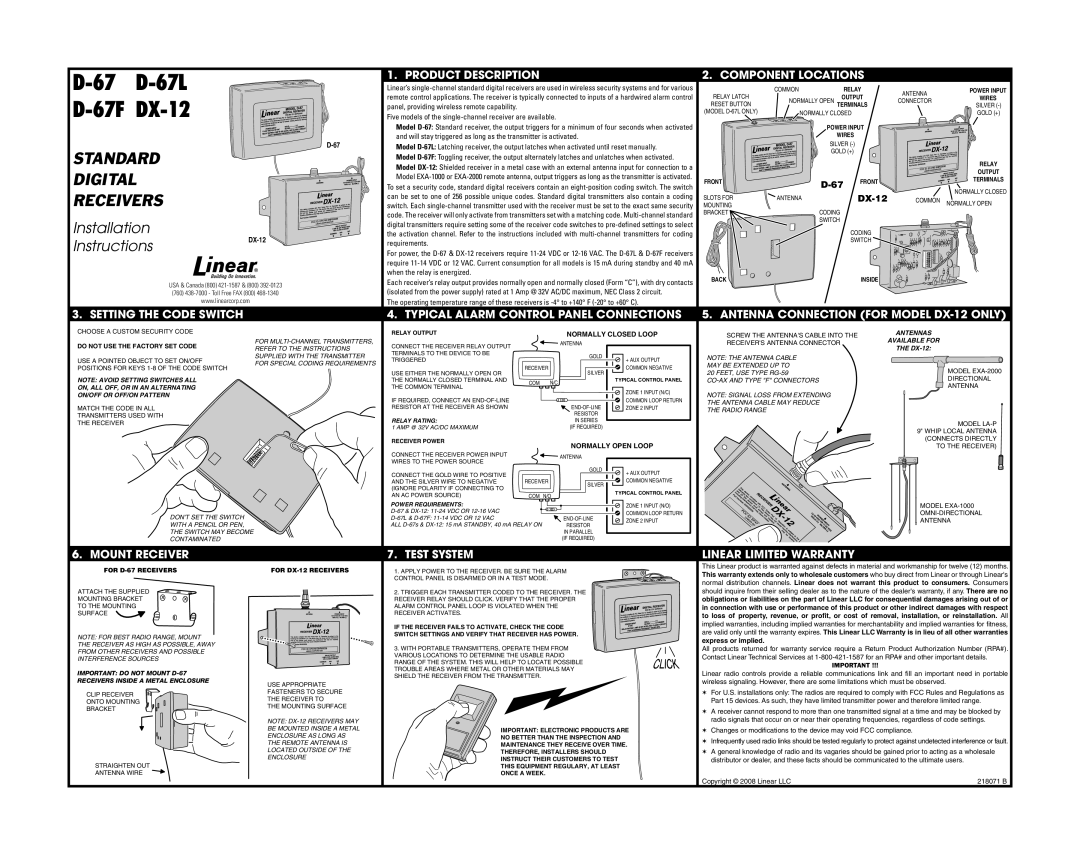
| 2. COMPONENT LOCATIONS |
|
| |||||
|
| Linear’s | RELAY LATCH | COMMON | RELAY | ANTENNA | POWER INPUT | |||||||
|
|
| remote control applications. The receiver is typically connected to inputs of a hardwired alarm control | NORMALLY OPEN | OUTPUT | CONNECTOR | WIRES | |||||||
|
| panel, providing wireless remote capability. |
|
|
|
| RESET BUTTON | TERMINALS | SILVER | |||||
|
| Five models of the |
|
| (MODEL | NORMALLY CLOSED |
|
| GOLD (+) | |||||
|
|
|
|
|
|
|
|
|
| |||||
|
|
|
| Model |
| POWER INPUT |
|
| ||||||
|
|
|
| and will stay triggered as long as the transmitter is activated. |
|
|
|
| WIRES |
|
|
| ||
|
|
| Model |
| SILVER |
|
|
| ||||||
STANDARD |
|
| GOLD (+) |
|
|
| ||||||||
|
| Model |
|
|
| RELAY | ||||||||
|
|
|
|
|
|
| ||||||||
|
|
|
|
|
|
|
|
|
| |||||
DIGITAL |
|
| Model |
|
|
|
|
| OUTPUT | |||||
|
| To set a security code, standard digital receivers contain an |
|
|
| |||||||||
|
|
|
|
| TERMINALS | |||||||||
|
|
|
| Model | FRONT |
|
| FRONT |
| |||||
|
|
|
|
|
|
|
|
|
|
|
|
| ||
RECEIVERS |
|
| can be set to one of 256 possible unique codes. Standard digital transmitters also contain a coding | SLOTS FOR | ANTENNA |
|
|
| NORMALLY CLOSED | |||||
|
|
| COMMON | NORMALLY OPEN | ||||||||||
|
| switch. Each | MOUNTING | CODING | ||||||||||
|
|
|
| code. The receiver will only activate from transmitters set with a matching code. | BRACKET |
|
|
| ||||||
Installation |
|
| digital transmitters require setting some of the receiver code switches to |
| SWITCH |
|
|
| ||||||
|
|
|
|
|
|
|
| |||||||
| the activation channel. Refer to the instructions included with |
|
| CODING |
|
| ||||||||
Instructions | requirements. |
|
|
|
|
|
| SWITCH |
|
| ||||
|
|
|
|
|
|
|
|
|
|
|
| |||
|
|
|
|
|
|
|
|
|
|
|
|
|
| |
|
|
|
| For power, the |
|
|
|
|
|
| ||||
|
|
|
| require |
|
|
|
|
|
| ||||
|
|
|
| when the relay is energized. |
|
|
|
| BACK |
|
| INSIDE |
|
|
| USA & Canada (800) | Each receiver’s relay output provides normally open and normally closed (Form “C”), with dry contacts |
|
|
|
| ||||||||
|
|
|
|
|
|
| ||||||||
| (isolated from the power supply) rated at 1 Amp @ 32V AC/DC maximum, NEC Class 2 circuit. |
|
|
|
|
|
| |||||||
| (760) |
|
|
|
|
|
| |||||||
| www.linearcorp.com |
| The operating temperature range of these receivers is |
|
|
|
|
|
| |||||
3. SETTING THE CODE SWITCH |
|
| 4. TYPICAL ALARM CONTROL PANEL CONNECTIONS | 5. ANTENNA CONNECTION (FOR MODEL | ||||||||||
CHOOSE A CUSTOM SECURITY CODE |
|
| RELAY OUTPUT |
| NORMALLY CLOSED LOOP | SCREW THE ANTENNA'S CABLE INTO THE |
| ANTENNAS |
| |||||
|
|
|
|
|
|
| ||||||||
DO NOT USE THE FACTORY SET CODE |
| FOR | CONNECT THE RECEIVER RELAY OUTPUT |
| ANTENNA |
|
| RECEIVER'S ANTENNA CONNECTOR |
| AVAILABLE FOR |
| |||
| REFER TO THE INSTRUCTIONS |
|
|
|
|
|
|
|
| THE |
| |||
|
|
| TERMINALS TO THE DEVICE TO BE |
|
|
|
|
|
|
|
|
| ||
|
|
| SUPPLIED WITH THE TRANSMITTER |
| GOLD |
|
| NOTE: THE ANTENNA CABLE |
|
|
|
| ||
USE A POINTED OBJECT TO SET ON/OFF |
| TRIGGERED |
|
| + AUX OUTPUT |
|
|
|
| |||||
| FOR SPECIAL CODING REQUIREMENTS |
|
|
|
|
|
|
| ||||||
|
|
|
| MAY BE EXTENDED UP TO |
|
|
|
| ||||||
POSITIONS FOR KEYS |
|
| RECEIVER |
|
| COMMON NEGATIVE |
|
|
|
| ||||
|
|
|
|
|
|
|
| MODEL | ||||||
|
| USE EITHER THE NORMALLY OPEN OR | SILVER |
| 20 FEET, USE TYPE |
|
|
| ||||||
|
|
|
|
|
|
|
|
|
| |||||
NOTE: AVOID SETTING SWITCHES ALL |
|
|
|
|
|
|
|
| DIRECTIONAL | |||||
|
| THE NORMALLY CLOSED TERMINAL AND | COM | N/C | TYPICAL CONTROL PANEL |
|
|
|
| |||||
ON, ALL OFF, OR IN AN ALTERNATING |
|
| THE COMMON TERMINAL |
|
|
|
|
|
|
| ANTENNA | |||
|
|
|
|
| ZONE 1 INPUT (N/C) |
|
|
|
|
| ||||
ON/OFF OR OFF/ON PATTERN |
|
|
|
|
|
| NOTE: SIGNAL LOSS FROM EXTENDING |
|
|
|
| |||
|
| IF REQUIRED, CONNECT AN |
|
|
| COMMON LOOP RETURN |
|
|
|
| ||||
|
|
|
|
|
|
| THE ANTENNA CABLE MAY REDUCE |
|
|
|
| |||
MATCH THE CODE IN ALL |
|
| RESISTOR AT THE RECEIVER AS SHOWN |
|
| ZONE 2 INPUT |
|
|
|
| ||||
|
|
|
| THE RADIO RANGE |
|
|
|
|
| |||||
TRANSMITTERS USED WITH |
|
| RELAY RATING: |
| RESISTOR |
|
|
|
|
|
|
|
| |
THE RECEIVER |
|
|
|
| IN SERIES |
|
|
|
|
|
|
| MODEL | |
|
|
| 1 AMP @ 32V AC/DC MAXIMUM |
| (IF REQUIRED) |
|
|
|
|
|
|
| ||
|
|
|
|
|
|
|
|
|
|
| 9" WHIP LOCAL ANTENNA | |||
|
|
|
|
|
|
|
|
|
|
|
|
| ||
|
|
|
| RECEIVER POWER |
| NORMALLY OPEN LOOP |
|
|
|
| (CONNECTS DIRECTLY | |||
|
|
|
|
|
|
|
|
| TO THE RECEIVER) | |||||
|
|
|
|
|
|
|
|
|
| |||||
|
|
|
| CONNECT THE RECEIVER POWER INPUT |
| ANTENNA |
|
|
|
|
|
|
|
|
|
|
|
| WIRES TO THE POWER SOURCE |
|
|
|
|
|
|
|
|
| |
|
|
|
|
|
|
|
|
|
|
|
|
|
| |
|
|
|
| CONNECT THE GOLD WIRE TO POSITIVE |
| GOLD |
| + AUX OUTPUT |
|
|
|
|
|
|
|
|
|
|
|
|
|
|
|
|
|
|
| ||
|
|
|
|
|
|
| COMMON NEGATIVE |
|
|
|
|
|
| |
|
|
|
| AND THE SILVER WIRE TO NEGATIVE | RECEIVER | SILVER |
|
|
|
|
|
|
| |
|
|
|
| (IGNORE POLARITY IF CONNECTING TO |
|
|
|
|
|
|
|
|
| |
|
|
|
|
|
| TYPICAL CONTROL PANEL |
|
|
|
|
|
| ||
|
|
|
| AN AC POWER SOURCE) | COM N/O |
|
|
|
|
|
| |||
|
|
|
|
|
|
|
|
|
|
|
| |||
|
|
|
| POWER REQUIREMENTS: |
|
|
| ZONE 1 INPUT (N/O) |
|
|
|
| MODEL | |
| DON'T SET THE SWITCH |
|
|
|
|
| COMMON LOOP RETURN |
|
|
|
| |||
|
|
|
|
| ZONE 2 INPUT |
|
|
|
| ANTENNA | ||||
| WITH A PENCIL OR PEN, |
|
| ALL | RESISTOR |
|
|
|
|
| ||||
|
|
|
|
|
|
|
|
|
|
| ||||
| THE SWITCH MAY BECOME |
|
|
| IN PARALLEL |
|
|
|
|
|
|
|
| |
| CONTAMINATED |
|
|
|
| (IF REQUIRED) |
|
|
|
|
|
|
|
|
6. MOUNT RECEIVER |
|
| 7. TEST SYSTEM |
|
|
|
| LINEAR LIMITED WARRANTY |
|
|
| |||
FOR |
| FOR | 1. APPLY POWER TO THE RECEIVER. BE SURE THE ALARM |
|
| This Linear product is warranted against defects in material and workmanship for twelve (12) months. | ||||||||
|
|
| This warranty extends only to wholesale customers who buy direct from Linear or through Linear's | |||||||||||
|
|
|
| CONTROL PANEL IS DISARMED OR IN A TEST MODE. |
|
|
| |||||||
|
|
|
|
|
|
| normal distribution channels. Linear does not warrant this product to consumers. Consumers | |||||||
|
|
|
|
|
|
|
|
| ||||||
ATTACH THE SUPPLIED |
|
| 2. TRIGGER EACH TRANSMITTER CODED TO THE RECEIVER. THE |
|
| should inquire from their selling dealer as to the nature of the dealer's warranty, if any. There are no | ||||||||
MOUNTING BRACKET |
|
| RECEIVER RELAY SHOULD CLICK. VERIFY THAT THE PROPER |
|
| obligations or liabilities on the part of Linear LLC for consequential damages arising out of or | ||||||||
TO THE MOUNTING |
|
| ALARM CONTROL PANEL LOOP IS VIOLATED WHEN THE |
|
| in connection with use or performance of this product or other indirect damages with respect | ||||||||
SURFACE |
|
|
| RECEIVER ACTIVATES. |
|
|
|
| to loss of property, revenue, or profit, or cost of removal, installation, or reinstallation. All | |||||
|
|
|
|
|
|
|
|
| ||||||
|
|
|
| IF THE RECEIVER FAILS TO ACTIVATE, CHECK THE CODE |
|
| implied warranties, including implied warranties for merchantability and implied warranties for fitness, | |||||||
|
|
|
|
|
| are valid only until the warranty expires. This Linear LLC Warranty is in lieu of all other warranties | ||||||||
NOTE: FOR BEST RADIO RANGE, MOUNT |
|
| SWITCH SETTINGS AND VERIFY THAT RECEIVER HAS POWER. |
|
| |||||||||
|
|
|
|
|
|
| express or implied. |
|
|
|
|
| ||
THE RECEIVER AS HIGH AS POSSIBLE, AWAY |
|
|
|
|
|
|
|
|
|
|
|
| ||
|
| 3. WITH PORTABLE TRANSMITTERS, OPERATE THEM FROM |
|
| All products returned for warranty service require a Return Product Authorization Number (RPA#). | |||||||||
FROM OTHER RECEIVERS AND POSSIBLE |
|
|
|
| ||||||||||
|
| VARIOUS LOCATIONS TO DETERMINE THE USABLE RADIO |
|
| Contact Linear Technical Services at | |||||||||
INTERFERENCE SOURCES |
|
|
|
| ||||||||||
|
| RANGE OF THE SYSTEM. THIS WILL HELP TO LOCATE POSSIBLE |
|
| ||||||||||
|
|
|
|
|
|
| IMPORTANT !!! |
|
| |||||
|
|
|
| TROUBLE AREAS WHERE METAL OR OTHER MATERIALS MAY |
|
|
|
|
| |||||
IMPORTANT: DO NOT MOUNT |
|
|
|
| Linear radio controls provide a reliable communications link and fill an important need in portable | |||||||||
|
| SHIELD THE RECEIVER FROM THE TRANSMITTER. |
|
|
| |||||||||
RECEIVERS INSIDE A METAL ENCLOSURE |
|
|
|
|
| wireless signaling. However, there are some limitations which must be observed. |
| |||||||
| USE APPROPRIATE |
|
|
|
|
|
| |||||||
|
|
|
|
|
|
|
|
|
|
|
|
|
| |
CLIP RECEIVER |
|
| FASTENERS TO SECURE |
|
|
|
|
| ✶ For U.S. installations only: The radios are required to comply with FCC Rules and Regulations as | |||||
|
| THE RECEIVER TO |
|
|
|
|
| Part 15 devices. As such, they have limited transmitter power and therefore limited range. | ||||||
ONTO MOUNTING |
|
|
|
|
|
| ||||||||
BRACKET |
|
| THE MOUNTING SURFACE |
|
|
|
|
| ✶ A receiver cannot respond to more than one transmitted signal at a time and may be blocked by | |||||
|
|
|
|
|
|
|
| |||||||
|
|
|
|
|
|
|
|
| ||||||
|
|
| NOTE: |
|
|
|
|
| radio signals that occur on or near their operating frequencies, regardless of code settings. | |||||
|
|
| BE MOUNTED INSIDE A METAL | IMPORTANT: ELECTRONIC PRODUCTS ARE | ✶ Changes or modifications to the device may void FCC compliance. |
| ||||||||
|
|
| ENCLOSURE AS LONG AS | NO BETTER THAN THE INSPECTION AND |
| ✶ Infrequently used radio links should be tested regularly to protect against undetected interference or fault. | ||||||||
|
|
| THE REMOTE ANTENNA IS | MAINTENANCE THEY RECEIVE OVER TIME. | ||||||||||
|
|
|
|
|
|
|
|
| ||||||
|
|
| LOCATED OUTSIDE OF THE | THEREFORE, INSTALLERS SHOULD |
|
| ✶ A general knowledge of radio and its vagaries should be gained prior to acting as a wholesale | |||||||
STRAIGHTEN OUT |
| ENCLOSURE | INSTRUCT THEIR CUSTOMERS TO TEST |
| distributor or dealer, and these facts should be communicated to the ultimate users. | |||||||||
|
| THIS EQUIPMENT REGULARY, AT LEAST |
|
|
|
|
|
|
| |||||
ANTENNA WIRE |
|
| ONCE A WEEK. |
|
|
|
|
|
|
|
|
| ||
|
|
|
|
|
|
|
|
| Copyright © 2008 Linear LLC |
|
|
| 218071 B | |