DEMO MANUAL DC101
SMART BATTERY CHARGER
OPERATIOU
Battery Removal, Thermistor Measurements: The charger periodically checks the thermistor in the battery through the
System Management Bus (SMBus)
When charge in the Smart Battery (SB) drops below 85% of the nominal capacity, it initiates communication over the SMBus every 64 seconds. After sending a START sequence, the battery addresses the Smart Battery charger and waits for an acknowledgment (ACK) from it. If the charger fails to acknowledge the word, the battery termi- nates further communication by placing a STOP sequence onto the SMBus. If the charger acknowledges (ACK) the reception of the first word, the battery continues the communication sequence and sends six more words to the charger. The complete current and voltage request communication sequence is as follows:
SDA
SCLK
0 | 0 | 0 | 1 |
START
1
START
address (12 hex)
Charging Current() command code (14 hex), current_LSB
current_MSB, address (12 hex)
Charging Voltage() command code (15 hex) voltage_LSB
voltage_MSB STOP
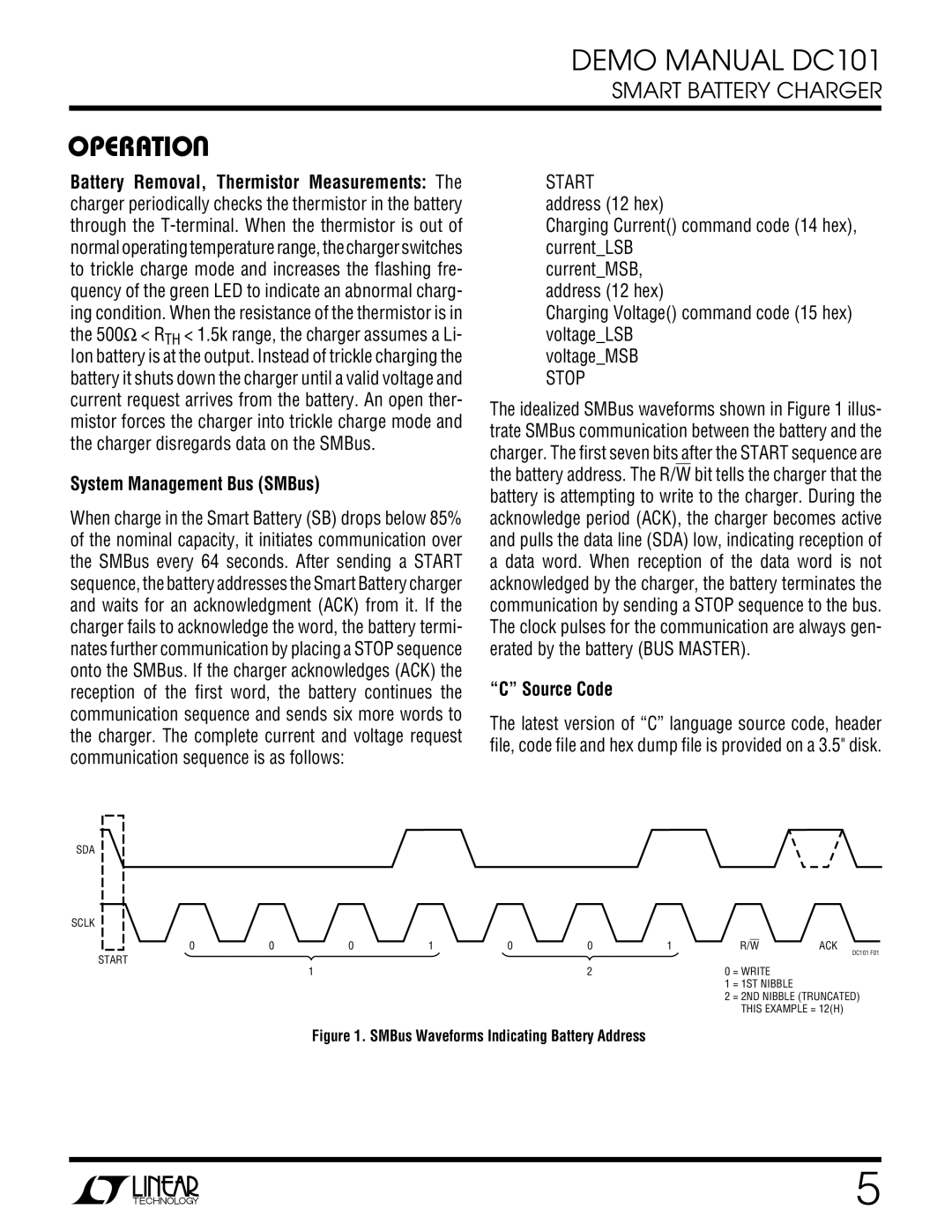
The idealized SMBus waveforms shown in Figure 1 illus- trate SMBus communication between the battery and the charger. The first seven bits after the START sequence are the battery address. The R/W bit tells the charger that the battery is attempting to write to the charger. During the acknowledge period (ACK), the charger becomes active and pulls the data line (SDA) low, indicating reception of a data word. When reception of the data word is not acknowledged by the charger, the battery terminates the communication by sending a STOP sequence to the bus. The clock pulses for the communication are always gen- erated by the battery (BUS MASTER).
“C” Source Code
The latest version of “C” language source code, header file, code file and hex dump file is provided on a 3.5" disk.
0 | 0 | 1 | R/W | ACK |
|
|
|
| DC101 F01 |
| 2 | 0 | = WRITE |
|
|
| 1 | = 1ST NIBBLE |
|
|
| 2 | = 2ND NIBBLE (TRUNCATED) | |
|
|
| THIS EXAMPLE = 12(H) | |
Figure 1. SMBus Waveforms Indicating Battery Address
5