PRINTER’S INSTRUCTIONS:
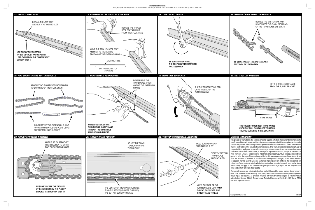
12. INSTALL FINAL BOLT | 13. REPOSITION THE TROLLEY STOP BOLT | 14. TIGHTEN ALL BOLTS | 15. REMOVE CHAIN FROM TURNBUCKLE |
INSTALL THE LAST BOLT |
|
| REMOVE THE MASTER LINK AND |
AND NUT INTO THE END SLOT |
|
| DISCONNECT THE CHAIN FROM EACH |
| REMOVE THE TROLEY |
| OF THE TURNBUCKLE |
|
|
| |
| STOP BOLT AND NUT |
|
|
| FROM THE STOCK |
|
|
| MOVE THE TROLLEY STOP BOLT |
|
|
USE ONE OF THE SHORTER | AND NUT TO THE BOTTOM |
|
|
SECTION OF THE EXTENSION RAIL |
|
| |
LEFT OVER FROM THE DISASSEMBLY |
|
|
|
DONE IN STEP 5 | STOP BOLT HOLE | BE SURE TO TIGHTEN ALL | BE SURE TO KEEP THE MASTER LINKS! |
| |||
|
| ||
|
| THE BOLTS ON THE EXTENSION | THEY WILL BE USED AGAIN |
| BOTTOM RAIL SECTION | RAIL ASSEMBLY |
|
|
|
| |
| (TOP VIEW) |
|
|
16. ADD SHORT CHAINS TO TURNBUCKLE | 17. REASSEMBLE TURNBUCKLE | 18. REINSTALL SPROCKET |
| 19. SET TROLLEY POSITION |
|
| REASSEMBLE THE |
|
|
ADD THE TWO SHORT EXTENSION CHAINS |
| TURNBUCKLE AFTER |
| SET THE TROLLEY DISTANCE |
| ADDING THE EXTENSION |
| ||
| SLIP THE SPROCKET HOLDER | FROM THE PULLEY BRACKET | ||
TO EACH END OF THE STOCK CHAIN |
| CHAINS | ||
|
| |||
|
|
| ONTO THE END OF THE |
|
|
|
| EXTENSION RAIL |
|
|
|
| 4 TO 6 INCHES |
| |
CONNECT THE TWO EXTENSION CHAINS | NOTE: ONE SIDE OF THE |
| THE TROLLEY MUST REST 4 TO 6 INCHES |
| |
TO THE TURNBUCKLE | TURNBUCKLE IS |
| FROM THE PULLEY BRACKET TO MATCH |
| |
THE MASTER LINKS SUPPLIED | THREAD, THE OTHER SIDE |
| THE |
| |
| IS |
|
| ||
|
|
|
| ||
20. ADJUST SPROCKET POSITION | 21. ADJUST CHAIN TENSION | 22. TIGHTEN TURNBUCKLE LOCKNUTS | LIMITED WARRANTY |
| |
|
|
| This product is warranted to the original consumer against defects in material and workmanship for | ||
ALIGN FLAT ON SPROCKET | ADJUST THE CHAIN | HOLD SCREWDRIVER IN | fi ve (5) years. Linear will repair, or at its option, replace, any device that it fi nds requires service under | ||
THIS DIRECTION TO MATCH | this warranty, and will return the repaired or replaced device to the consumer at Linear’s cost. Devices | ||||
TENSION WITH THE | TURNBUCKLE SLOT | ||||
FLAT ON OPERATOR SHAFT | must be sent to Linear for service at owner’s expense. This warranty does not apply to damage to | ||||
TURNBUCKLE |
| ||||
|
| the product from negligence, abuse, abnormal usage, misuse, accidents, normal wear or tear or due | |||
|
|
| |||
|
| TIGHTEN THE TWO | to failure to follow Seller’s instructions, or arising from improper installation, storage or maintenance. | ||
|
| In no event will Linear be responsible for incidental, compensatory, punitive, consequential, indirect, | |||
|
| TURNBUCKLE | special or other damages. The remedies provided by this warranty are exclusive. Some states do not | ||
|
| LOCKING NUTS | allow the exclusion or limitation of incidental and consequential damages, so the above limitation | ||
|
|
| or exclusion may not apply to you. Any warranties implied by law are limited to the time periods set | ||
|
|
| forth above. Some states do not allow limitations on how long an implied warranty lasts, so the above | ||
|
|
| limitation may not apply to you. This warranty gives you specifi c legal rights, and you may also have | ||
|
|
| other rights which vary from state to state. |
| |
|
|
| For warranty service and shipping instructions contact Linear at the phone number shown below. In | ||
|
|
| order to be protected by this warranty, save your proof of purchase and send a copy with equipment | ||
|
|
| should repair be required. All products returned for warranty service require a Return Product | ||
|
|
| Authorization Number (RPA#). Contact Linear Technical Services at | ||
|
|
| and other important details. |
| |
BE SURE TO KEEP THE TROLLEY |
| NOTE: ONE SIDE OF THE |
|
| |
THE CENTER OF THE CHAIN SHOULD BE | TURNBUCKLE IS |
|
| ||
AT |
|
| |||
SLIGHTLY ABOVE (NO MORE THAN 1/8") | THREAD, THE OTHER SIDE |
|
| ||
BRACKET AS SHOWN IN STEP 19 |
|
| |||
THE BOTTOM EDGE OF THE RAIL | IS |
|
| ||
| Copyright © 2008 Linear LLC | 228232 A | |||
|
|
| |||