AM-SEK / LIN-501C Quick Start Guide
General LIN-501C Module Configuration
1.From the Windows START menu, select RUN.
2.Enter COMMAND (or CMD) into the OPEN: field and press OK. The DOS command prompt window will open.
3.Enter IPCONFIG and press ENTER. The current Windows IP configuration for the PC will be displayed. Write down the IP Address, Subnet Mask, and Default Gateway address numbers. Keep the window open for reference or enter EXIT to close it.
4.Insert the utilities CD into the PC’s
✓✓ NOTE: The monitor.exe application has several buttons and options that are not used for
5.Press the INVITE button. The application will display a list of all the
✓✓ NOTE: The monitor.exe application can only detect modules located on the LAN side of the same router as the PC.
6.From the displayed list, select the IP address of the module to program. (To help to identify modules, checking the LOCATE box will cause the selected module to beep.) Press CONFIG.
7.The configuration for the selected module displays showing the fixed MAC address and currently programmed IP, Gateway, and Subset Mask addresses.
8.A static IP address is required for the
9.To allow the module to communicate with the PC on the same network, the first three octets (xxx.xxx.xxx) of the LIN‑501C module’sIPaddressmusttobesettothesameastheprogramming PC’s IP address. Set the first three octets for the module’s addresses into the IP ADDRESS field. To avoid conflicts with existing network devices, choose a high number from
✓✓ NOTE: The IP address for each
10.Set the Gateway and Subnet Mask addresses to the same as the programming PC.
11.Write the settings in the log sheet to document the access network module and note the modules address settings.
12.Enter a name for HOST NAME to identify the module or the access network installation.
13.Press CONFIG NOW to send the configuration to the module.
14.The
PC Virtual COM Port Configuration
1.Launch the Vcom488.exe installation program from the utility CD. Install the virtual COM port program on to the PC as instructed by the installation wizard.
2.Select the virtual COM port(s) that will be used to connect to the LIN‑501C module(s). Press OK
✓✓
COM ports
3.In the SERIAL/IP CONTROL PANEL select a COM port to use to connect to a module. Be sure the CONNECT TO SERVER box is checked. Enter the module’s IP address in the IP ADDRESS field. Enter port 4660 into the PORT NUMBER field.
4.Press CONFIGURATION WIZARD. The Configuration window will be displayed. To test the PC’s COM port
5.The status area will show the progress of the test. Green check marks indicate that the connection is OK. Red check marks indicate failures in the test. If the test fails, verify the address and port settings of both the module and the PC. Be sure the first three octets of the LIN‑501C module’s IP address match the PC. Press USE SETTINGS to exit the wizard.
6.Repeat Steps 2 through 5 for any additional
7.When finished, press CLOSE to exit the SERIAL/IP CONTROL PANEL. (The
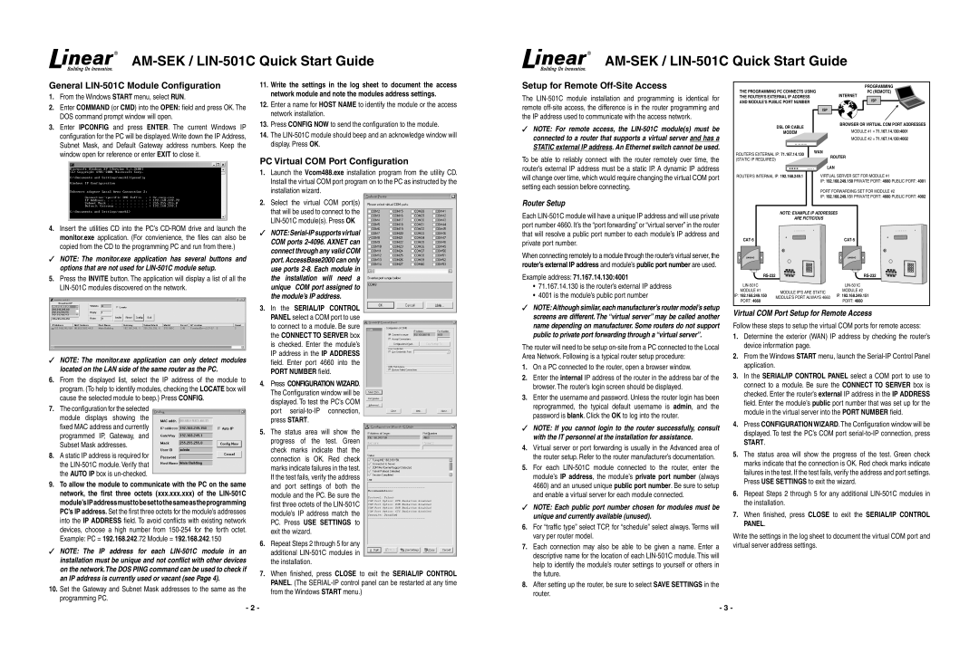
Setup for Remote Off-Site Access
The
✓✓ NOTE: For remote access, the
To be able to reliably connect with the router remotely over time, the router’s external IP address must be a static IP. A dynamic IP address will change over time, which would require changing the virtual COM port setting each session before connecting.
Router Setup
Each
When connecting remotely to a module through the router’s virtual server, the router’s external IP address and module’s public port number are used.
Example address: 71.167.14.130:4001
•71.167.14.130 is the router’s external IP address
•4001 is the module’s public port number
✓✓ NOTE: Although similar, each manufacturer’s router model’s setup screens are different. The “virtual server” may be called another name depending on manufacturer. Some routers do not support public to private port forwarding through a “virtual server”.
The router will need to be setup
1.On a PC connected to the router, open a browser window.
2.Enter the internal IP address of the router in the address bar of the browser. The router’s login screen should be displayed.
3.Enter the username and password. Unless the router login has been reprogrammed, the typical default username is admin, and the password is blank. Click the OK to log into the router.
✓✓ NOTE: If you cannot login to the router successfully, consult with the IT personnel at the installation for assistance.
4.Virtual server or port forwarding is usually in the Advanced area of the router setup. Refer to the router manufacturer’s documentation.
5.For each
✓✓ NOTE: Each public port number chosen for modules must be unique and currently available (unused).
6.For “traffic type” select TCP, for “schedule” select always. Terms will vary per router model.
7.Each connection may also be able to be given a name. Enter a descriptive name for the location of each
8.After setting up the router, be sure to select SAVE SETTINGS in the router.
THE PROGRAMMING PC CONNECTS USING | PROGRAMMING | |
PC (REMOTE) | ||
THE ROUTER'S EXTERNAL IP ADDRESS |
| INTERNET |
AND MODULE'S PUBLIC PORT NUMBER |
| ISP |
| ISP |
|
DSL OR CABLE |
| BROWSER OR VIRTUAL COM PORT ADDRESSES |
| MODULE #1 = 71.167.14.130:4001 | |
MODEM |
| |
|
| MODULE #2 = 71.167.14.130:4002 |
ROUTER'S EXTERNAL IP: 71.167.14.130 | WAN | ROUTER |
| ||
(STATIC IP REQUIRED) |
| |
|
| |
| LAN |
ROUTER'S INTERNAL IP: 192.168.249.1 | VIRTUAL SERVER SET FOR MODULE #1 |
| IP: 192.168.249.150 PRIVATE PORT: 4660 PUBLIC PORT: 4001 |
| PORT FORWARDING SET FOR MODULE #2 |
| IP: 192.168.249.151 PRIVATE PORT: 4660 PUBLIC PORT: 4002 |
NOTE: EXAMPLE IP ADDRESSES | |
ARE FICTICIOUS | |
| |||
| |||
MODULE #1 | MODULE IP'S ARE STATIC | MODULE #2 | |
IP: 192.168.249.150 | IP: 192.168.249.151 | ||
MODULE'S PORT ALWAYS 4660 | |||
PORT: 4660 | PORT: 4660 | ||
|
Virtual COM Port Setup for Remote Access
Follow these steps to setup the virtual COM ports for remote access:
1.Determine the exterior (WAN) IP address by checking the router’s device information page.
2.From the Windows START menu, launch the
3.In the SERIAL/IP CONTROL PANEL select a COM port to use to connect to a module. Be sure the CONNECT TO SERVER box is checked. Enter the router’s external IP address in the IP ADDRESS field. Enter the module’s public port number that was set up for the module in the virtual server into the PORT NUMBER field.
4.Press CONFIGURATION WIZARD.The Configuration window will be displayed. To test the PC’s COM port
START.
5.The status area will show the progress of the test. Green check marks indicate that the connection is OK. Red check marks indicate failures in the test. If the test fails, verify the address and port settings. Press USE SETTINGS to exit the wizard.
6.Repeat Steps 2 through 5 for any additional
7.When finished, press CLOSE to exit the SERIAL/IP CONTROL PANEL.
Write the settings in the log sheet to document the virtual COM port and virtual server address settings.
- 2 -
- 3 -