|
| DESCRIPTION The | |||
SX | motion detector with a | ||||
transmitter designed for security applications. |
| ||||
|
| FORMAT! | The PIR detects motion in its detection pattern by measuring the | ||
SUPERVISED WIRELESS | |||||
infrared emission levels of objects that it “sees”. If the infrared levels | |||||
PASSIVE INFRARED |
| change quickly, as when a person moves across the detection | |||
| pattern, the PIR will recognize the change as an intrusion. | ||||
MOTION DETECTOR |
| A selectable “pulse count” circuit controls the PIR’s triggering of the | |||
| transmitter. As a person moves across the detection pattern, the PIR | ||||
|
|
| registers one pulse as each “finger” of the detection pattern is | ||
Installation Instructions |
| crossed. The | |||
| number of pulses occur during the selected time, the PIR will trigger | ||||
|
|
| the transmitter, sending an alarm signal. A lockout timer prevents the | ||
|
|
| transmitter from triggering more often than once every 2 minutes | ||
|
|
| when constant motion is detected. The pulse counting and timing | ||
|
|
| options are selected with the OPTION switch. |
| |
|
|
| The unit is supervised for low battery, alarm and status reporting. The | ||
|
|
|
| ||
|
|
| security receiver. The transmitter sends hourly status reports. A test | ||
|
|
| report can be sent by pressing the test button. |
| |
|
|
| Coding switches are not required or used in this transmitter. Each | ||
|
|
| transmitter is | ||
| (760) | format, there are more than sixteen million codes possible. | |||
|
|
| |||
USA & Canada (800) |
|
| |||
| Toll Free FAX (800) |
|
| ||
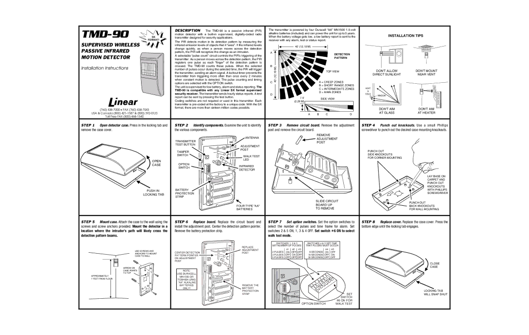
STEP 1 | Open detector case. Press in the locking tab and | STEP 2 Identify components. Examine the unit to identify | |||
remove the case cover. |
| the various components. |
| ||
|
|
|
| ANTENNA | |
|
|
| TRANSMITTER |
| |
|
|
| TEST BUTTON | ADJUSTMENT | |
|
|
|
| ||
|
|
| TAMPER | POST | |
|
|
|
| ||
|
|
| SWITCH | WALK TEST | |
|
|
|
| ||
|
| OPEN |
| LED | |
|
| OPTION |
| ||
|
| CASE | INFRARED | ||
|
|
| SWITCH | ||
|
|
| DETECTOR | ||
|
|
|
| ||
|
| PUSH IN | BATTERY |
| |
|
| LOCKING TAB | PROTECTION |
| |
|
| STRIP |
| ||
|
|
|
| ||
|
|
|
| FOUR TYPE "AA" | |
|
|
|
| BATTERIES | |
STEP 5 | Mount case. Attach the case to the wall using the | STEP 6 Replace board. Replace the circuit board and | |||
screws and screw anchors provided. Mount the detector in a | install the adjustment post. Center the detection pattern pointer. | ||||
location where the intruder’s path will likely cross the | Remove the battery protection strip. |
| |||
detection pattern beams. |
|
|
| ||
|
|
|
| REPLACE | |
|
| USE SCREWS AND | CENTER DETECTION | ADJUSTMENT | |
|
| POST | |||
|
| ANCHORS TO MOUNT | |||
|
| CASE TO WALL | PATTERN POINTER |
| |
|
|
| ON ADJUSTMENT |
| |
|
|
| POST |
| |
| ARROW ON |
|
|
| |
| CASE POINTS | NOTE: |
| ||
| TO TOP |
| USE DURACELL |
| |
APPROXIMATELY |
|
| |||
| MN1500 OR |
| |||
7 FEET FROM FLOOR |
| TOSHIBA LR6G |
| ||
|
|
|
| ||
|
|
| "AA" ALKALINE | REMOVE THE | |
|
|
| BATTERIES | ||
|
|
| ONLY! | BATTERY | |
|
|
|
| PROTECTION | |
|
|
|
| STRIP | |
The transmitter is powered by four Duracell “AA” MN1500
![]()
![]() 40' (12.19 M)
40' (12.19 M) ![]()
![]()
A |
| DETECTION | |
|
| ||
|
| PATTERN | |
B | M) |
| |
| TOP VIEW | ||
| 40' (12.19 | ||
C | A = CREEP ZONES | ||
| |||
|
| B = SHORT RANGE ZONES | |
|
| C = INTERMEDIATE ZONES | |
|
| D = MAIN ZONES |
D
7.5' |
| SIDE VIEW |
|
(2.29 M) |
|
| |
|
|
| |
A | B | C | D |
STEP 3 Remove circuit board. Remove the adjustment post and remove the circuit board.
REMOVE
![]() ADJUSTMENT
ADJUSTMENT
POST
SLIDE CIRCUIT
BOARD UP
TO REMOVE
STEP 7 Set option switches. Set the option switches to select the number of pulses and time frame for alarm. Set switches 2 & 5 ON, 1, 3 & 4 OFF. Set switch #6 ON to select walk test mode.
SWITCHES 1, 2 & 3 |
|
| SWITCHES 4 & 5 SET TIME | ||||||||||
SET NUMBER OF PULSES |
| THAT PULSES MUST OCCUR | |||||||||||
2 PULSES |
| #1 |
| #2 |
|
| #3 |
| 8 SECONDS |
| #4 |
| #5 |
|
|
|
|
|
| ||||||||
| ON |
| OFF |
| OFF |
|
| ON |
| OFF | |||
3 PULSES |
| OFF |
| ON |
| OFF |
| 16 SECONDS |
| OFF |
| ON | |
5 PULSES |
| OFF |
| OFF |
| OFF |
| 32 SECONDS |
| OFF |
| OFF | |
| SET |
| SWITCH |
OPTION SWITCH | #6 ON FOR |
WALK TEST |
INSTALLATION TIPS
DON'T ALLOW | DON'T MOUNT |
DIRECT SUNLIGHT | NEAR VENT |
HEAT |
|
& |
|
COLD |
|
WINDOW |
|
DON'T AIM | DON'T AIM |
AT GLASS | AT HEATER |
STEP 4 Punch out knockouts. Use a small Phillips screwdriver to punch out the desired case mounting knockouts.
PUNCH OUT
SIDE KNOCKOUTS
FOR CORNER MOUNTING
LAY BASE ON
CARPET AND
PUNCH OUT
KNOCKOUTS
WITH PHILLIPS
SCREWDRIVER
PUNCH OUT
BACK KNOCKOUTS
FOR WALL MOUNTING
STEP 8 Replace cover. Replace the case cover. Press the bottom edge until the locking tab engages.
CLOSE
CASE
LOCKING TAB
WILL SNAP SHUT