Chapter 1
Product Overview
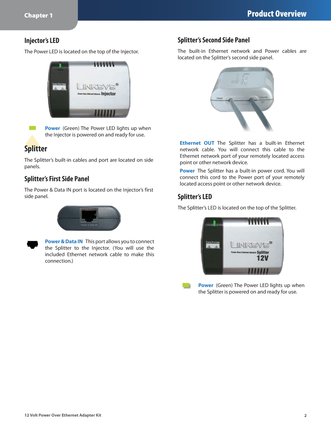
Injector’s LED
The Power LED is located on the top of the Injector.
Power (Green) The Power LED lights up when the Injector is powered on and ready for use.
Splitter
The Splitter’s
Splitter’s First Side Panel
The Power & Data IN port is located on the Injector’s first side panel.
Power & Data IN This port allows you to connect the Splitter to the Injector. (You will use the included Ethernet network cable to make this connection.)
Splitter’s Second Side Panel
The
Ethernet OUT The Splitter has a
Power The Splitter has a
Splitter’s LED
The Splitter’s LED is located on the top of the Splitter.
Power (Green) The Power LED lights up when the Splitter is powered on and ready for use.
12 Volt Power Over Ethernet Adapter Kit | 2 |