MFH-I&S-02

If this water heater is installed in a closed water supply system, such as the one

WARNING

having a back-flow preventer in the cold water supply, provisions shall be made

to control thermal expansion. DO NOT operate this water heater in a closed

NOTE: Some models may already be equipped or supplied with a

combination temperature and pressure relief valve. Verify that the

system without provisions for controlling thermal expansion. Your water supplier

combination temperature and pressure relief valve complies with local

or local plumbing inspector should be contacted on how to control this situation.

codes. If the combination temperature and pressure relief valve does


After installation of the water lines, open the main water supply valve and fill

not comply with local codes, replace it with one that does. Follow the

installation instructions above on this page.

the water heater. While the water heater is filling, open several hot water


faucets to allow air to escape from the water system. When a steady stream

Install a discharge line so that water discharged from the combination

of water flows through the faucets, close them and check all water connections

temperature and pressure relief valve will exit within six (6) inches

for possible leaks. NEVER OPERATE THE WATER HEATER WITHOUT FIRST

(15.2 cm) above, or any distance below the structural floor and cannot

BEING CERTAIN IT IS FILLED WITH WATER.

contact any live electrical part. The discharge line is to be installed to


allow for complete drainage of both the combination temperature and


pressure relief valve and the discharge line. The discharge opening


WARNING


must not be subjected to blockage or freezing. DO NOT thread, plug

Hydrogen gas can be produced in an operating water heater that


or cap the discharge line. It is recommended that a minimum clearance

has not had water drawn from the tank for a long period of time


of four (4) inches (10.2 cm) be provided on the side of the water

(generally two weeks or more). Hydrogen gas is extremely flammable.


heater for servicing and maintenance of the combination temperature

To prevent the possibility of injury under these conditions, we


and pressure relief valve.

recommend the hot water faucet to be open for several minutes at the


kitchen sink before you use any electrical appliance which is connected


Do not place a valve between the combination temperature and pressure

to the hot water system. If hydrogen is present, there will be an


relief valve and the tank.

unsual sound such as air escaping through the pipes as hot water


begins to flow. Do not smoke or have open flame near the faucet at


the time it is open.


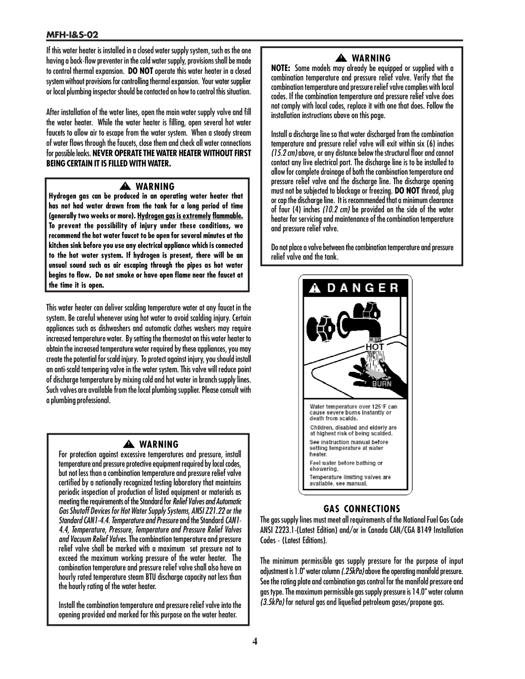
This water heater can deliver scalding temperature water at any faucet in the


system. Be careful whenever using hot water to avoid scalding injury. Certain


appliances such as dishwashers and automatic clothes washers may require


increased temperature water. By setting the thermostat on this water heater to


obtain the increased temperature water required by these appliances, you may


create the potential for scald injury. To protect against injury, you should install


an anti-scald tempering valve in the water system. This valve will reduce point


of discharge temperature by mixing cold and hot water in branch supply lines.


Such valves are available from the local plumbing supplier. Please consult with


a plumbing professional.


WARNING

For protection against excessive temperatures and pressure, install temperature and pressure protective equipment required by local codes, but not less than a combination temperature and pressure relief valve certified by a nationally recognized testing laboratory that maintains periodic inspection of production of listed equipment or materials as meeting the requirements of the Standard for Relief Valves and Automatic Gas Shutoff Devices for Hot Water Supply Systems, ANSI Z21.22 or the Standard CAN1-4.4. Temperature and Pressure and the Standard CAN1- 4.4, Temperature, Pressure, Temperature and Pressure Relief Valves and Vacuum Relief Valves. The combination temperature and pressure relief valve shall be marked with a maximum set pressure not to exceed the maximum working pressure of the water heater. The combination temperature and pressure relief valve shall also have an hourly rated temperature steam BTU discharge capacity not less than the hourly rating of the water heater.

Install the combination temperature and pressure relief valve into the opening provided and marked for this purpose on the water heater.

GAS CONNECTIONS

The gas supply lines must meet all requirements of the National Fuel Gas Code ANSI Z223.1-(Latest Edition) and/or in Canada CAN/CGA B149 Installation Codes - (Latest Editions).

The minimum permissible gas supply pressure for the purpose of input adjustment is 1.0" water column (.25kPa) above the operating manifold pressure. See the rating plate and combination gas control for the manifold pressure and gas type. The maximum permissible gas supply pressure is 14.0" water column (3.5kPa) for natural gas and liquefied petroleum gases/propane gas.

4

Page 4
Image 4
Lochinvar MFH-I&S-02 service manual GAS Connections, Being Certain IT is Filled with Water

MFH-I&S-02 specifications

The Lochinvar MFH-I&S-02 is a sophisticated Modular Floor Heat Integrated System known for its innovative design and efficiency in residential and commercial heating applications. As part of Lochinvar's commitment to providing high-performance solutions, the MFH-I&S-02 incorporates a variety of advanced technologies and characteristics that set it apart in the market.

One of the main features of the MFH-I&S-02 is its modular design, which allows for flexible installation options. This system can be easily tailored to meet the specific heating needs of any space, ensuring optimal comfort and energy efficiency. The modular approach not only simplifies installation but also enhances the system's versatility, making it suitable for both new constructions and retrofitting in existing buildings.

The MFH-I&S-02 employs an innovative heat exchanger that maximizes thermal efficiency. With a stainless steel construction, the heat exchanger is designed to withstand high temperatures and pressures, ensuring durability and longevity. This high-efficiency design translates to lower energy consumption, leading to cost savings for the end-user and a reduced carbon footprint.

In addition to its advanced heat exchanger, the MFH-I&S-02 includes smart controls and monitoring capabilities. These features enable users to easily manage their heating system through intuitive interfaces, whether via a wall-mounted display or a smartphone app. This connectivity allows for real-time monitoring and adjustments, facilitating proactive maintenance and optimization of heating performance.

The MFH-I&S-02 also utilizes variable speed technology in its pumps and fans, enhancing energy efficiency further. By adjusting operating speeds based on demand, the system minimizes unnecessary energy use while maintaining consistent heating. This adaptability not only improves comfort levels but also significantly contributes to overall system efficiency.

Furthermore, with a focus on sustainability, the MFH-I&S-02 is designed to work seamlessly with renewable energy sources, such as solar thermal systems. This integration capability allows it to maximize energy use from renewable sources, aligning with modern energy goals and regulations.

In summary, the Lochinvar MFH-I&S-02 is a cutting-edge heating solution that combines modular design, high-efficiency heat exchange, smart technology, and renewable energy compatibility. Its advancements in engineering and user-centered features make it an ideal choice for those seeking an effective and flexible heating system in today's energy-conscious environment.