1. Package Contents
1 x CCD Color Day/
Night Camera
1 x Camera Stand
1 x 100’ (30m) DIN
Extension Cable
2. Installing the Camera
Note: Test the cameras prior to selecting a permanent mounting location by temporarily connecting the Cameras and Cables to the System.
1.Mount the camera stand to the desired mounting surface. Attach the camera to the supplied stand.
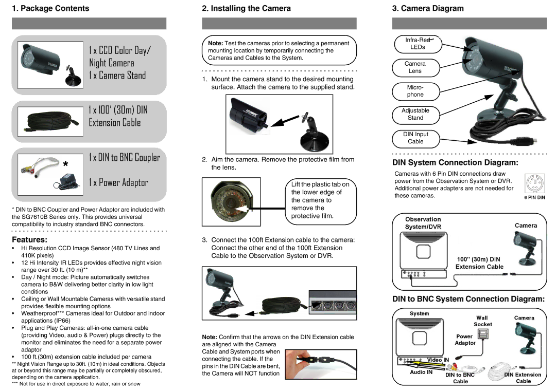
3. Camera Diagram
![]()
LEDs
Camera
Lens
Micro- phone
Adjustable
Stand
DIN Input
Cable
*
1 x DIN to BNC Coupler
1 x Power Adaptor
2.Aim the camera. Remove the protective film from the lens.
Lift the plastic tab on the lower edge of the camera to
DIN System Connection Diagram:
Cameras with 6 Pin DIN connections draw power from the Observation System or DVR. Additional power adapters are not needed for these cameras.
*DIN to BNC Coupler and Power Adaptor are included with the SG7610B Series only. This provides universal compatibility to industry standard BNC connectors.
Features:
•Hi Resolution CCD Image Sensor (480 TV Lines and 410K pixels)
•12 Hi Intensity IR LEDs provides effective night vision range over 30 ft. (10 m)**
•Day / Night mode: Picture automatically switches camera to B&W delivering better clarity in low light conditions
•Ceiling or Wall Mountable Cameras with versatile stand provides flexible mounting options
•Weatherproof*** Cameras ideal for Outdoor and indoor applications (IP66)
•Plug and Play Cameras:
•100 ft.(30m) extension cable included per camera
**Night Vision Range up to 30ft. (10m) in ideal conditions. Objects at or beyond this range may be partially or completely obscured, depending on the camera application.
***Not for use in direct exposure to water, rain or snow
remove the protective film.
3.Connect the 100ft Extension cable to the camera: Connect the other end of the 100ft Extension Cable to the Observation System or DVR.
Note: Confirm that the arrows on the DIN Extension cable are aligned with the Camera
Cable and System ports when connecting the cable. If the pins in the DIN Cable are bent, the Camera will NOT function