|
|
|
|
|
|
|
|
|
| s |
|
|
|
|
|
| MSerie | ||||
|
|
|
| 4Q |
|
|
|
| ||
|
|
| - |
|
|
|
|
|
| |
| S |
|
|
|
|
| UIDE |
| ||
H |
|
|
|
|
|
|
|
| ||
S |
|
|
|
|
|
|
|
| ||
|
|
|
|
| KSET |
|
| |||
|
| UIC |
|
|
|
|
| |||
| Q |
|
|
|
|
|
| P1 |
| |
|
|
|
|
|
|
| TE |
| ||
|
|
|
|
|
| S |
|
|
| |
Quad Surveillance System
with 4 CCD Indoor/Outdoor cameras*
Time | Tools | Skills - Easy | ||
Under 10 Minutes* |
| Hand Tools | easy | |
| Plug & Play connectors, On | |||
* Installation time may vary based | ||||
| screen set up | |||
on application and camera cabling |
| |||
|
| |||
Getting Started
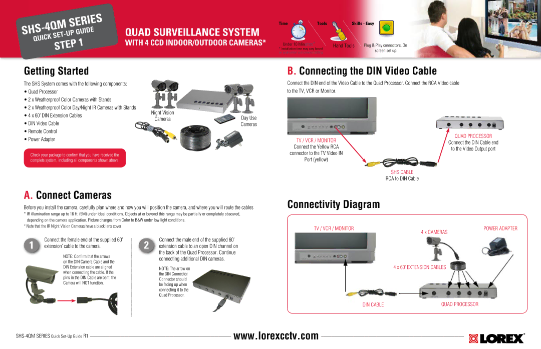
The SHS System comes with the following components:
•Quad Processor
•2 x Weatherproof Color Cameras with Stands
•2 x Weatherproof Color Day/Night IR Cameras with Stands
•4 x 60’ DIN Extension Cables
•DIN Video Cable
•Remote Control
•Power Adapter
Check your package to confirm that you have received the complete system, including all components shown above.
Night Vision
CamerasDay Use
Cameras
B. Connecting the DIN Video Cable
Connect the DIN end of the Video Cable to the Quad Processor. Connect the RCA VIdeo cable to the TV, VCR or Monitor.
TV / VCR / MONITOR | QUAD PROCESSOR | |
Connect the DIN Cable end | ||
Connect the Yellow RCA | ||
to the Video Output port | ||
connector to the TV Video IN | ||
| ||
Port (yellow) |
|
SHS CABLE
RCA to DIN Cable
A. Connect Cameras
Before you install the camera, carefully plan where and how you will position the camera, and where you will route the cables
*IR illumination range up to 16 ft. (5M) under ideal conditions. Objects at or beyond this range may be partially or completely obscured, depending on the camera application. Picture changes from Color to B&W under low light conditions.
*Note that the IR Night Vision Cameras have a black lens cover.
Connectivity Diagram
TV / VCR / MONITOR | 4 x CAMERAS | POWER ADAPTER |
|
|
1 | Connect the female end of the supplied 60’ |
extension’ cable to the camera. |
NOTE: Confirm that the arrows on the DIN Camera Cable and the DIN Extension cable are aligned when connecting the cable. If the pins in the DIN Cable are bent, the Camera will NOT function.
Connect the male end of the supplied 60’
2 extension cable to an open DIN channel on the back of the Quad Processor. Continue connecting additional DIN cameras.
NOTE: The arrow on the DIN Connector Connector should be facing up when connecting it to the Quad Processor.
4 x 60’ EXTENSION CABLES
DIN CABLE | QUAD PROCESSOR |
www.lorexcctv.com |
