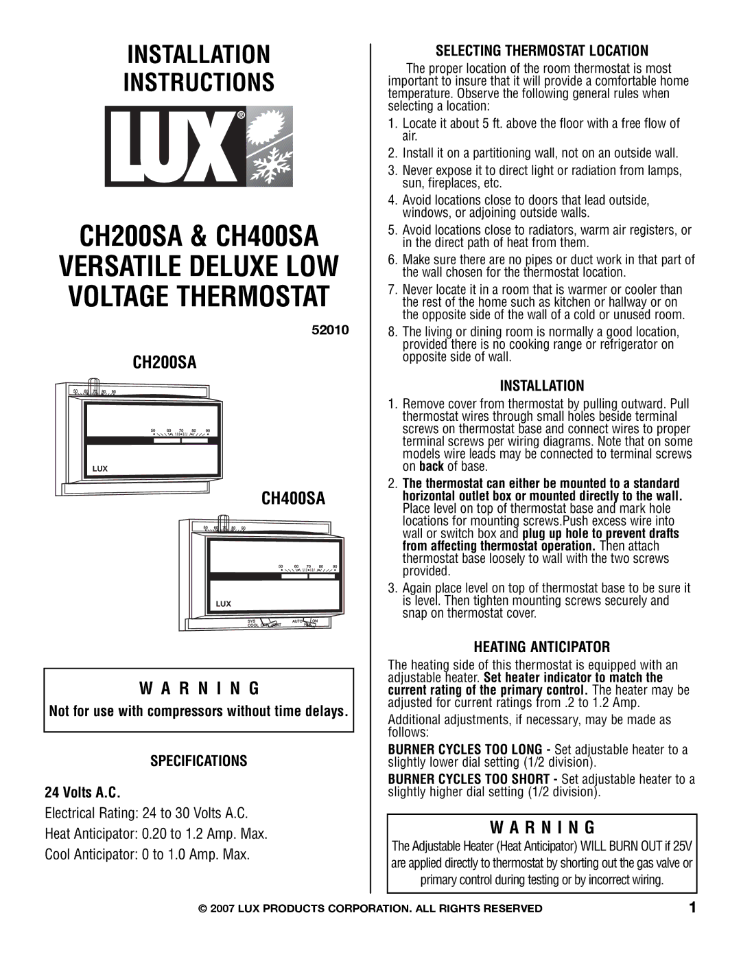
CH200SA, CH400SA specifications
Lux Products has garnered a reputation for delivering innovative and reliable home comfort products, and their CH400SA and CH200SA thermostats stand as prime examples of this commitment. Designed to enhance user experience while ensuring energy efficiency, these programmable thermostats come packed with features that cater to the needs of modern homeowners.The Lux CH400SA is a versatile thermostat that offers a four-programmer capability, allowing users to customize heating and cooling schedules according to their daily routines. With a user-friendly interface, it simplifies the programming process, making it accessible to everyone, regardless of technical expertise. The large, backlit display ensures that readings can easily be seen, even in low light conditions.
One of the standout features of the CH400SA is its Smart Recovery technology. This innovative feature learns how long your heating or cooling system takes to reach the desired temperature and starts the process in advance. This ensures that the home is at the perfect temperature when you arrive, enhancing comfort while optimizing energy efficiency. Furthermore, the thermostat is compatible with most HVAC systems, providing flexibility for different household setups.
On the other hand, the Lux CH200SA is designed for those who prefer simple, straightforward controls without the complexity of advanced programming. It features a basic interface with an easy-to-read display, making temperature adjustments quick and hassle-free. The CH200SA allows users to switch between heating and cooling modes with ease, and an adjustable temperature range ensures that the thermostat can accommodate various heating systems.
Both models come equipped with a temperature hold function, which allows users to maintain a specific temperature for an extended period without reprogramming. This is particularly useful during vacations or when unexpected changes in plans arise. Additionally, the energy-saving capabilities of the CH400SA and CH200SA can lead to significant savings on energy bills, benefiting not just the wallet but also the environment by reducing overall energy consumption.
Durability and reliability are also key characteristics of these thermostats. Built with high-quality materials, they are designed to withstand the rigors of daily use while maintaining accuracy and performance over time. Both the CH400SA and CH200SA represent Lux Products' commitment to creating reliable, user-friendly solutions that prioritize home comfort and energy efficiency. Whether you choose the advanced features of the CH400SA or the straightforward simplicity of the CH200SA, you can rest assured that you are enhancing the comfort of your home effectively.