
PSD111 specifications
The Lux Products PSD111 is a high-performance programmable thermostat designed specifically for homeowners looking to optimize energy efficiency and maintain comfortable living conditions. With its user-friendly interface and advanced features, the PSD111 is ideal for both new users and those looking to upgrade their current home heating and cooling solutions.One of the standout features of the PSD111 is its 7-day programming capability, allowing users to set different schedules for each day of the week. This flexibility ensures that the heating and cooling systems operate efficiently according to the homeowner's lifestyle, reducing energy waste during hours when heating or cooling is not needed. With up to four programmable periods per day, users can easily customize the temperature for mornings, days, evenings, and nights.
Another significant characteristic of the PSD111 is its intuitive touchscreen display, which makes it easy to navigate and set up schedules. The large LCD screen displays the current temperature, programmed settings, and time, providing clarity and convenience at a glance. The backlit screen enhances visibility, making it usable in low light conditions.
The PSD111 also employs advanced technology to enhance energy savings. Its Energy Star certification ensures that the thermostat meets strict efficiency guidelines, helping homeowners reduce their energy bills. The adaptive recovery feature learns how long it takes to heat or cool the home and adjusts the start time of the heating or cooling system accordingly. This ensures that the desired temperature is reached at the set time without unnecessary energy consumption.
Additionally, the PSD111 includes a temporary hold feature, which allows users to override the programmed schedule for a specified period with the option to return to the regular schedule afterward. This is particularly useful for unexpected changes in plans or when welcoming guests.
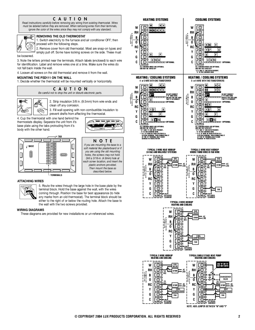
Installation is straightforward, with compatibility for most 24V heating and cooling systems, making it an accessible option for a wide range of homes. The durable design ensures longevity, and with Lux Products' commitment to quality, users can expect a reliable thermostat that performs efficiently for years to come.
In summary, the Lux Products PSD111 stands out for its programmable versatility, user-centric design, energy-saving technologies, and compatibility with various heating and cooling systems, making it an exceptional choice for homeowners seeking to enhance comfort and efficiency in their living spaces.