With an
Figure 1 / Figura 1
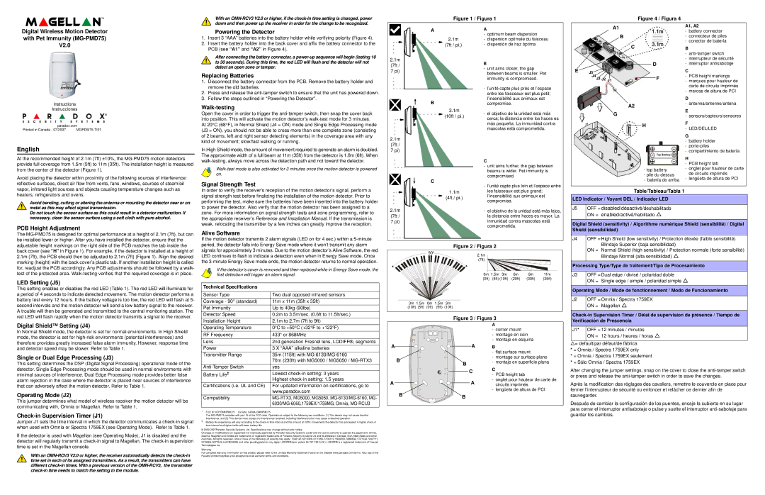
Figure 4 / Figura 4 |
Digital Wireless Motion Detector with Pet Immunity
V2.0
Instructions
Instrucciones
paradox.com
Printed in Canada - 07/2007 |
English
At the recommended height of 2.1m (7ft) ±10%, the
Avoid placing the detector within proximity of the following sources of interference: reflective surfaces, direct air flow from vents, fans, windows, sources of steam/oil vapor, infrared light sources and objects causing temperature changes such as heaters, refrigerators and ovens.
Avoid bending, cutting or altering the antenna or mounting the detector near or on metal as this may affect signal transmission.
Do not touch the sensor surface as this could result in a detector malfunction. If necessary, clean the sensor surface using a soft cloth with pure alcohol.
PCB Height Adjustment
Powering the Detector
1.Insert 3 “AAA” batteries into the battery holder while verifying polarity (Figure 4).
2.Insert the battery holder into the back cover and affix the battery connector to the PCB (see “A1” and “A2” in Figure 4).
After connecting the battery connector, a
Replacing Batteries
1.Disconnect the battery connector from the PCB. Remove the battery holder and remove the old batteries.
2.Press and release the
3.Follow the steps outlined in “Powering the Detector”.
Walk-testing
Open the cover in order to trigger the
In High Shield mode, the amount of movement required to generate an alarm is doubled. The approximate width of a full beam at 11m (35ft) from the detector is 1.8m (6ft). When
Signal Strength Test
In order to verify the receiver's reception of the motion detector’s signal, perform a signal strength test before finalizing the installation of the motion detector. Prior to performing the test, make sure the batteries have been inserted into the battery holder to power the detector. Also verify that the motion detector has been assigned to a zone. For more information on signal strength tests and zone programming, refer to the appropriate receiver’s Reference and Installation Manual. If the transmission is weak, relocating the transmitter by a few inches can greatly improve the reception.
A
2.1m
(7ft / pi.)
2.1m (7ft / 7 pi)
B
3.1m


 (10ft / pi.)
2.1m (7ft / 7 pi)
C
1.1m
(4ft / pi.)
2.1m (7ft / 7 pi)
A
-optimum beam dispersion
-dispersion optimale du faisceau
-dispersión de haz óptima
B
-unit aims closer, the gap between beams is smaller. Pet immunity is compromised.
-l’unité capte plus près et l’espace entre les faisceaux est plus petit; l’insensibilité aux animaux est compromise.
-el objetivo de la unidad está más cerca; la distancia entre los haces es más pequeña. La inmunidad contra mascotas está comprometida.
C
-unit aims further, the gap between beams is wider. Pet immunity is compromised.
-l’unité capte plus loin et l’espace entre les faisceaux est plus grand; l’insensibilité aux animaux est compromise.
-el objetivo de la unidad está más lejos, la distancia entre haces es mayor. La inmunidad contra mascotas está comprometida.
|
|
| A1 | A1, A2 | |||||||||
|
|
|
|
|
|
|
|
|
|
|
| - battery connector | |
|
|
| B | - connecteur de piles | |||||||||
|
|
|
|
| C | - conector de batería | |||||||
|
|
|
|
| B |
| |||||||
|
|
|
|
|
|
|
|
|
|
|
| - | |
|
|
|
|
|
|
|
|
|
|
|
| - | interrupteur de sécurité |
E |
|
|
|
|
|
|
|
| D | - | interruptor antisabotaje | ||
|
|
|
|
|
|
|
| ||||||
J5 |
|
|
|
|
|
|
|
|
|
| C |
| |
| J4J3 J2 | J1 |
|
|
|
|
|
|
| F | - PCB height markings | ||
|
|
|
|
|
|
|
|
|
|
| - marques pour hauteur de | ||
|
|
|
|
|
|
|
|
|
|
|
|
| carte de circuits imprimés |
|
|
|
|
|
|
|
|
|
|
|
| - marcas de altura de PCI | |
|
|
|
|
|
|
|
|
|
|
|
| D |
|
|
|
| A2 | - antenna/antenne/antena | |||||||||
|
|
| E |
| |||||||||
|
|
| G |
| |||||||||
|
|
| - sensors/capteurs/sensores | ||||||||||
|
|
|
|
|
|
| H | F |
| ||||
|
|
|
|
|
|
|
| ||||||
|
|
|
|
|
|
|
|
|
|
|
| - LED/DEL/LED | |
|
|
|
|
|
|
|
|
|
|
|
| G |
|
|
|
|
|
|
|
|
|
|
|
|
| - | battery holder |
|
|
|
|
|
|
|
|
|
|
|
| ||
|
|
|
|
|
|
|
|
|
|
|
| - | |
|
|
|
|
|
|
|
|
|
|
|
| - compartimiento de batería | |
|
|
|
|
|
|
|
|
|
|
|
| H |
|
|
|
|
|
|
|
|
|
|
|
|
| - PCB height tab | |
|
|
|
|
|
|
| - top battery | - onglet pour hauteur de carte | |||||
|
|
|
|
|
|
| - pile du dessus |
| de circuits imprimés | ||||
|
|
|
|
|
|
| - batería de arriba | - lengüeta de altura de PCI | |||||
Table/Tableau/Tabla 1
LED Indicator / Voyant DEL / Indicador LED
J5 OFF = disabled/désactivé/deshabilitado
ON = enabled/activé/habilitado U
Digital Shield (sensitivity) / Algorithme numérique Shield (sensibilité) / Digital Shield (sensibilidad)
The
LED Setting (J5)
This setting enables or disables the red LED (Table 1). The red LED will illuminate for a period of 4 seconds to indicate detected movement. The motion detector performs a battery test every 12 hours. If the battery voltage is too low, the red LED will flash at 5- second intervals and the motion detector will send a low battery signal to the receiver. A trouble will then be generated and transmitted to the central monitoring station. The red LED will flash rapidly when the motion detector transmits a signal to the receiver.
Digital Shield™ Setting (J4)
In Normal Shield mode, the detector is set for normal environments. In High Shield mode, the detector is set for
Single or Dual Edge Processing (J3)
This setting determines the DSP (Digital Signal Processing) operational mode of the detector. Single Edge Processing mode should be used in normal environments with minimal sources of interference. Dual Edge Processing mode provides better false alarm rejection in the case where the detector is placed near sources of interference that can adversely affect the motion detector. Refer to Table 1.
Operating Mode (J2)
This jumper determines what model of wireless receiver the motion detector will be communicating with, Omnia or Magellan. Refer to Table 1.
Check-in Supervision Timer (J1)
Jumper J1 sets the time interval in which the detector communicates a
If the detector is used with Magellan (see Operating Mode), J1 is disabled and the detector will regularly transmit a
With an
Alive Software
If the motion detector transmits 2 alarm signals (LED on for 4 sec.) within a
If the detector’s cover is removed and then replaced while in Energy Save mode, the first detection will trigger an alarm signal.
Technical Specifications
Sensor Type | Two dual opposed infrared sensors |
Coverage - 90° (standard) | 11m x 11m (35ft x 35ft) |
Pet Immunity | Up to 40kg (90lbs) |
Detector Speed | 0.2m to 3.5m/sec. (0.6ft to 11.5ft/sec.) |
Installation Height | 2.1m to 2.7m (7ft to 9ft) |
Operating Temperature | 0°C to +50°C (+32°F to +122°F) |
RF Frequency | 433* or 868MHz |
Lens | 2nd generation Fresnel lens, LODIFF®, segments |
Power | 3 X “AAA” alkaline batteries |
Transmitter Range | 35m (115ft) with |
| 70m (230ft) with MG5000 / MG5050 / |
yes | |
Battery Life† | Lowest |
| Highest |
Certifications (i.e. UL and CE) | For updated information on certifications, go to |
| www.paradox.com |
Compatibility | |
|
|
* FCC ID: KDYOMNPMD75 Canada:
The
†Battery life expectancy will vary according to the
©
Changes or modifications on equipment not expressly approved by Paradox Security Systems could void the user’s authority to operate the equipment. Omnia, Spectra, Magellan and Shield are trademarks or registered trademarks of Paradox Security Systems Lts and its affiliates in Canada, the United Staes and other countries. All rights reserved. One or more of the following US patents may apply: 7046142, 6215399, 6111256, 6104319, 5920259, 5886632, 5721542, 5287111, 5119069, 5077549 and RE39406 and other pending patents may apply. LODIFF® lens: patent #4,787,722 (U.S.). LODIFF® is a registered trademark of Fresnel Technologies Inc.
Warranty
For complete warranty information on this product please refer to the Limited Warranty Statement found on the website www.paradox.com/terms. Your use of the Paradox product signifies your acceptance of all warranty terms and conditions.
Figure 2 / Figura 2
|
|
|
90° | 2.1m | |
|
| |
|
| (7ft) |
|
|
|
|
|
|
|
|
|
|
|
|
| 0m 1.5m | 3m | 6m | 9m | 11m |
| |
|
|
|
|
|
|
|
|
|
|
|
|
| (0ft) | (5ft) (10ft) | (20ft) | (30ft) | (35ft) |
| |
|
| 3m 1.5m | 0m | 1.5m | 3m |
|
|
|
|
|
| ||||||||
|
| (10ft) (5ft) | (0ft) | (5ft) | (10ft) |
|
|
|
|
|
| ||||||||
|
|
|
|
|
|
|
|
|
|
|
|
|
|
|
|
|
|
| |
|
|
|
|
|
|
|
|
|
| Figure 3 / Figura 3 |
|
|
|
|
| ||||
|
|
|
|
|
|
|
|
|
|
|
|
|
| A |
|
|
|
|
|
|
|
|
|
|
|
|
|
|
|
|
|
|
| - corner mount |
|
|
| ||
|
|
|
|
|
|
|
|
|
|
|
|
|
| - montage en coin |
|
| |||
|
|
|
|
|
|
|
|
|
|
|
|
|
| - montaje en esquina |
|
| |||
A |
|
|
|
|
|
|
|
|
|
|
|
| A | B |
|
|
|
|
|
|
|
|
|
|
|
|
|
|
|
|
|
| |||||||
|
|
|
|
|
|
|
|
|
|
|
|
|
| - flat surface mount |
|
| |||
|
| B |
|
|
|
|
|
|
|
|
| - montage sur surface plane |
| ||||||
|
|
|
|
|
|
| B | - montaje en superficie plana |
| ||||||||||
|
|
|
|
|
|
|
|
|
| C |
|
|
|
|
| ||||
|
|
|
|
|
|
|
|
|
|
| C |
|
|
|
|
| |||
|
|
|
|
|
|
|
|
|
|
|
|
|
|
|
| ||||
|
|
|
|
|
|
|
|
|
|
|
|
|
| - PCB height tab |
|
|
| ||
A |
|
|
|
|
|
|
|
|
|
| A | - onglet pour hauteur de carte de |
| ||||||
|
|
|
|
|
|
|
|
| circuits imprimés |
|
| ||||||||
- lengüeta de altura de PCI
BB
J4 | OFF = High Shield (low sensitivity) / Protection élevée (faible sensibilité) |
| Blindaje Superior (baja sensibilidad) |
| ON = Normal Shield (high sensitivity) / Protection normale (forte sensibilité) |
| Blindaje Normal (alta sensibilidad) U |
|
|
Processing Type/Type de traitement/Tipo de Procesamiento | |
|
|
J3 | OFF = Dual edge / divisé / polaridad doble |
| ON = Single edge / simple / polaridad simple U |
|
|
Operating Mode / Mode de fonctionnement / Modo de Funcionamiento | |
|
|
J2 | OFF = Omnia / Spectra 1759EX |
| ON = Magellan U |
|
|
J1* OFF = 12 minutes / minutos
ON = 12 hours / heures / horas U
U= default/par défaut/de fábrica
*= Omnia / Spectra 1759EX only
*= Omnia / Spectra 1759EX seulement
*= Sólo Omnia / Spectra 1759EX
After changing the jumper settings, snap on the cover to close the
Après la modification des réglages des cavaliers, remettre le couvercle en place pour fermer l’interrupteur de sécurité ou enfoncer et relâcher ce dernier afin de sauvegarder.
Después de cambiar la configuración de los puentes, encaje la cubierta en su lugar para cerrar el interruptor antisabotaje o pulse y suelte el interruptor