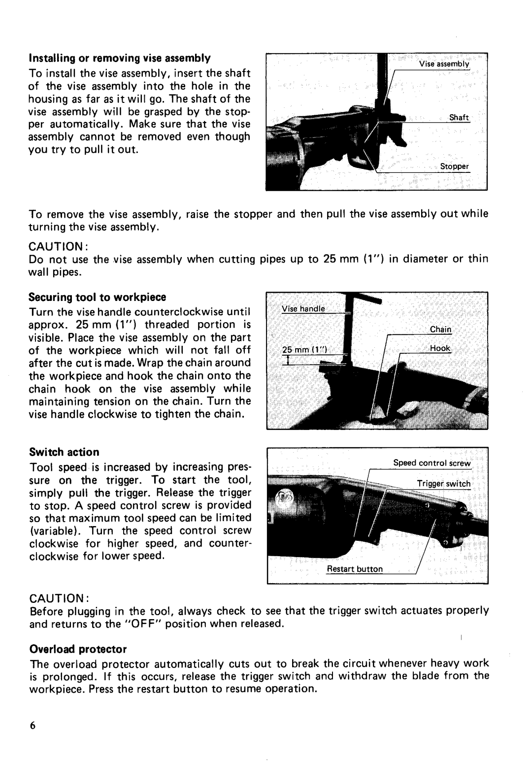
Installing or removing vise assembly
To install the vise assembly, insert the shaft of the vise assembly into the hole in the housing as far as it will go. The shaft of the vise assembly will be grasped by the stop- per automatically. Make sure that the vise assembly cannot be removed even though you try to pull it out.
To remove the vise assembly, raise the stopper and then pull the vise assembly out while turning the vise assembly.
CAUTION :
Do not use the vise assembly when cutting pipes up to 25 mm (1") in diameter or thin wall pipes.
Securing tool t o workpiece
Turn the vise handle counterclockwise until approx. 25 mm (1") threaded portion is visible. Place the vise assembly on the part of the workpiece which will not fall off after the cut is made. Wrap the chain around the workpiece and hook the chain onto the chain hook on the vise assembly while maintaining tension on the chain. Turn the vise handle clockwise to tighten the chain.
Switch action
Tool speed is increased by increasing pres- sure on the trigger. To start the tool, simply pull the trigger. Release the trigger to stop. A speed control screw is provided so that maximum tool speed can be limited (variable). Turn the speed control screw clockwise for higher speed, and counter- clockwise for lower speed.
CAUTION :
Before plugging in the tool, always check to see that the trigger switch actuates properly and returns to the "OFF" position when released.
Overload protector
The overload protector automatically cuts out to break the circuit whenever heavy work is prolonged. If this occurs, release the trigger switch and withdraw the blade from the workpiece. Press the restart button to resume operation.
6