P 7/ 14
 Repair
[3]DISASSEMBLY/ASSEMBLY
[3]-3. Hammer Section
DISASSEMBLING
(1)Disassemble Hammer case section from the machine. (Figs. 2 and 3)
(2)Remove Hammer from Hammer case complete. (Fig. 4)
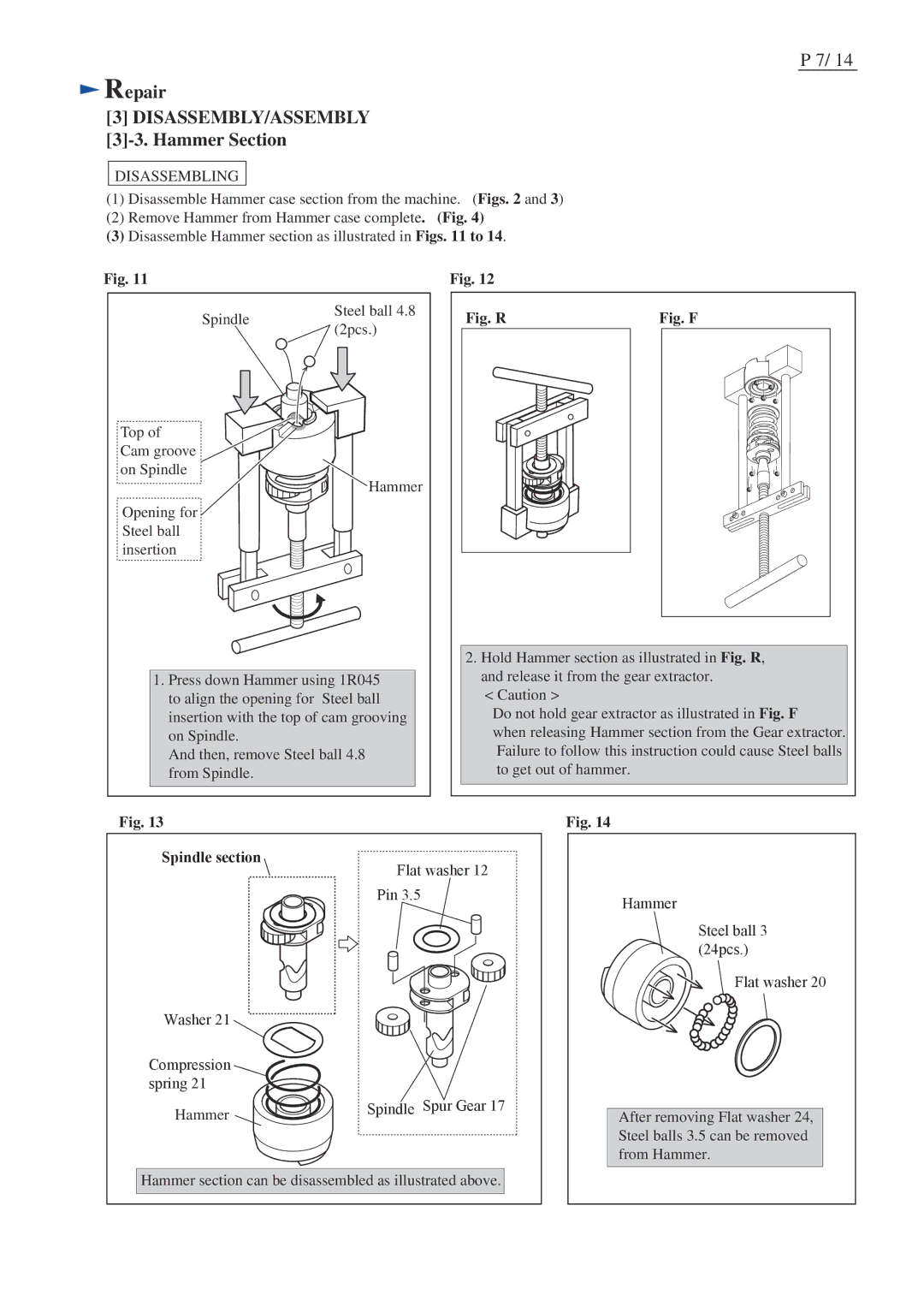
(3)Disassemble Hammer section as illustrated in Figs. 11 to 14.
Fig. 11
Spindle | Steel ball 4.8 | |
(2pcs.) | ||
|
Top of Cam groove on Spindle
Hammer
Opening for Steel ball
insertion
1.Press down Hammer using 1R045 to align the opening for Steel ball insertion with the top of cam grooving on Spindle.
And then, remove Steel ball 4.8 from Spindle.
Fig. 12
Fig. R | Fig. F | ||||||
|
|
|
|
|
|
|
|
|
|
|
|
|
|
|
|
|
|
|
|
|
|
|
|
|
|
|
|
|
|
|
|
|
|
|
|
|
|
|
|
|
|
|
|
|
|
|
|
|
|
|
|
|
|
|
|
|
|
|
|
|
|
|
|
|
|
|
|
|
|
|
|
2.Hold Hammer section as illustrated in Fig. R, and release it from the gear extractor.
<Caution >
Do not hold gear extractor as illustrated in Fig. F
when releasing Hammer section from the Gear extractor. Failure to follow this instruction could cause Steel balls to get out of hammer.
Fig. 13
Spindle section
Flat washer 12
Pin 3.5
Washer 21
Compression spring 21
Hammer | Spindle Spur Gear 17 |
Hammer section can be disassembled as illustrated above.
Fig. 14
Hammer
Steel ball 3 (24pcs.)
Flat washer 20
After removing Flat washer 24, Steel balls 3.5 can be removed from Hammer.
