P 3/ 6
 Repair
[2]DISASSEMBLY/ASSEMBLY
[3]-1. Hammer case section
DISASSEMBLING
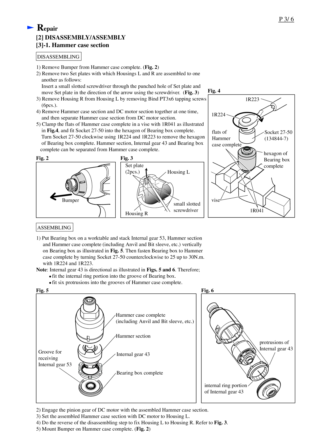
1)Remove Bumper from Hammer case complete. (Fig. 2)
2)Remove two Set plates with which Housings L and R are assembled to one another as follows:
Insert a small slotted screwdriver through the punched hole of Set plate and move Set plate in the direction of the arrow using the screwdriver. (Fig. 3)
3)Remove Housing R from Housing L by removing Bind PT3x6 tapping screws (6pcs.).
4)Remove Hammer case section and DC motor section together at one time, and then separate Hammer case section from DC motor section.
5)Clamp the flats of Hammer case complete in a vise with 1R041 as illustrated in Fig.4, and fit Socket
Fig. 4
1R223 ![]()
1R224
flats of | Socket |
Hammer | |
case complete |
|
hexagon of
Fig. 2
Bumper
Fig. 3
Set plate |
|
(2pcs.) | Housing L |
| small slotted |
Housing R | screwdriver |
|
Bearing box complete
vise![]()
1R041
ASSEMBLING
1)Put Bearing box on a worktable and stack Internal gear 53, Hammer section and Hammer case complete (including Anvil and Bit sleeve, etc.) vertically on Bearing box as illustrated in Fig. 5. Then fasten Bearing box to Hammer case complete by turning Socket
Note: Internal gear 43 is directional as illustrated in Figs. 5 and 6. Therefore;
![]() fit the internal ring portion into the groove of Bearing box.
fit the internal ring portion into the groove of Bearing box. ![]() fit six protrusions into the grooves of Hammer case complete.
fit six protrusions into the grooves of Hammer case complete.
Fig. 5 | Fig. 6 |
Hammer case complete
(including Anvil and Bit sleeve, etc.) Hammer section
Groove for | Internal gear 43 | |
receiving | ||
| ||
Internal gear 53 |
| |
| Bearing box complete |
protrusions of Internal gear 43
internal ring portion ![]() of Internal gear 43
of Internal gear 43
2)Engage the pinion gear of DC motor with the assembled Hammer case section.
3)Set the assembled Hammer case section with DC motor to Housing L.
4)Do the reverse of the disassembling step to fix Housing L to Housing R. Refer to Fig. 3.
5)Mount Bumper on Hammer case complete. (Fig. 2)
