INSTALLATION
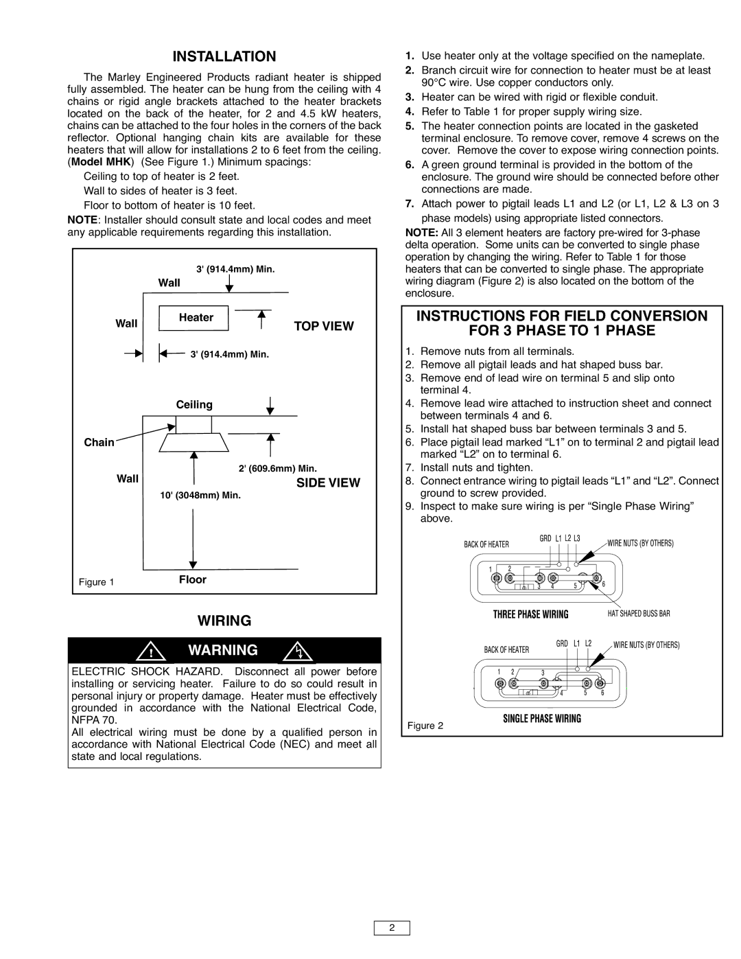
The Marley Engineered Products radiant heater is shipped fully assembled. The heater can be hung from the ceiling with 4 chains or rigid angle brackets attached to the heater brackets located on the back of the heater, for 2 and 4.5 kW heaters, chains can be attached to the four holes in the corners of the back reflector. Optional hanging chain kits are available for these heaters that will allow for installations 2 to 6 feet from the ceiling. (Model MHK) (See Figure 1.) Minimum spacings:
Ceiling to top of heater is 2 feet. Wall to sides of heater is 3 feet. Floor to bottom of heater is 10 feet.
NOTE: Installer should consult state and local codes and meet any applicable requirements regarding this installation.
| 3' (914.4mm) Min. |
| Wall |
Wall | Heater |
TOP VIEW | |
| 3' (914.4mm) Min. |
Ceiling
Chain
Wall | 2' (609.6mm) Min. |
SIDE VIEW | |
| 10' (3048mm) Min. |
| Floor |
Figure 1 |
WIRING
a
! WARNING
ELECTRIC SHOCK HAZARD. Disconnect all power before installing or servicing heater. Failure to do so could result in personal injury or property damage. Heater must be effectively grounded in accordance with the National Electrical Code, NFPA 70.
All electrical wiring must be done by a qualified person in accordance with National Electrical Code (NEC) and meet all state and local regulations.
1.Use heater only at the voltage specified on the nameplate.
2.Branch circuit wire for connection to heater must be at least 90°C wire. Use copper conductors only.
3.Heater can be wired with rigid or flexible conduit.
4.Refer to Table 1 for proper supply wiring size.
5.The heater connection points are located in the gasketed terminal enclosure. To remove cover, remove 4 screws on the cover. Remove the cover to expose wiring connection points.
6.A green ground terminal is provided in the bottom of the enclosure. The ground wire should be connected before other connections are made.
7.Attach power to pigtail leads L1 and L2 (or L1, L2 & L3 on 3 phase models) using appropriate listed connectors.
NOTE: All 3 element heaters are factory
INSTRUCTIONS FOR FIELD CONVERSION
FOR 3 PHASE TO 1 PHASE
1.Remove nuts from all terminals.
2.Remove all pigtail leads and hat shaped buss bar.
3.Remove end of lead wire on terminal 5 and slip onto terminal 4.
4.Remove lead wire attached to instruction sheet and connect between terminals 4 and 6.
5.Install hat shaped buss bar between terminals 3 and 5.
6.Place pigtail lead marked “L1” on to terminal 2 and pigtail lead marked “L2” on to terminal 6.
7.Install nuts and tighten.
8.Connect entrance wiring to pigtail leads “L1” and “L2”. Connect ground to screw provided.
9.Inspect to make sure wiring is per “Single Phase Wiring” above.
Figure 2
2