2. Standby Switch
The Standby Switch is used in conjunction with the Power Switch (item 1) to ‘warm up’ the amplifier before use and to prolong the life of the output valves.
When powering up the amplifier always engage the Power Switch (item 1) first. This allows the application of the voltage required to heat the valves to their correct operating temperature. After about 2 minutes, when the valves are up to the correct temperature, the Standby Switch can be engaged. Upon doing this the H.T. (High Tension) which is the high voltage required by the output valves to pass signal (and hence produce sound) is applied.
To prolong valve life, the Standby Switch alone should be used to turn the amplifier on and off during breaks in a performance. Also, upon full power down, always disengage the Standby Switch prior to the main Power Switch (item 1).
3. Indicator
The Indicator will be lit when your amplifier is on and will not be lit when the amplifier is switched off.
4. Presence Control
Adds higher frequencies to the guitar tone, creating crispness and bite. Turning this up will make the sound more cutting and ‘present’.
5. Bass Control
Controls the amount of low frequencies or bottom end in your tone.
sound in relation to the other tone controls. Experimentation is the best way to achieve your desired sounds.)
8. High Treble Loudness 1
Controls the overall output level of Channel 1. Note: This channel is voiced for a higher treble response than Channel 2.
9. Normal Loudness 2
Controls the overall output level of Channel 2. Note: Channel 2 is voiced for normal response.
10. Input Jack
Connects the guitar to Channel 1.
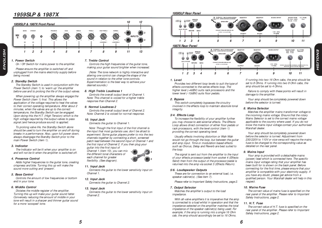
Note: Though the first input of the first channel is the input that most guitarists use, don’t be afraid to experiment. Some guitar players prefer to mix the two channels together by connecting a short, screened patch lead between the second input of Channel 1 and
the first input of Channel 2. If you then plug your | |
guitar into the first input of | | | |
Channel 1 (item 10), you can mix 1 | | 2 |
the different tonal characters of | | INPUTS | |
each channel for greater | | |
1 | | 2 |
flexibility. (See diagram). | |
| | |
11. Input Jack
Connects the guitar to the lower sensitivity input on Channel 1.
12. Input Jack
Connects the guitar to Channel 2.
1. Level
Provides two different loop levels to suit the type of effects connected to the series effects loop. The higher level (+4dBV) suits rack processors and the lower level (-10dBV) suits floor pedals.
2. Bypass
This switch completely bypasses the circuitry involved in the effects loop to maintain absolute tonal integrity.
3/4. Effects Loop
To increase the flexibility of your amplifier further you may choose to add external effects. The Effects Loop allows direct connection of either floor pedals or rack processors, with the level control (item 1) providing the correct operating level.
Usually effects involving distortion or Wah Wah would not go through the loop, but between the guitar and amp input. Time or modulation based effects such as Chorus, Delay and Reverb are best suited to the loop.
The signal is sent out from the amplifier to the input of your effects processor/pedal from socket 4 (Effects Send) then from the output of the processor/pedal is returned into the amp via socket 3 (Effects Return).
5/6. Loudspeaker Outputs
These are for connection to an external load, i.e. speaker cabinet(s). (See item 7).
Please refer to Important Safety Instructions, page 2.
If running into two 16 Ohm cabs, the amp should be set to 8 Ohms. If running into two 8 Ohm cabs, the amp should be set to 4 Ohms.
Failure to comply with these points will result in damage to the amplifier.
Your amp should be completely powered down before the selector is turned.
8. Mains Selector
Matches the amplifier mains transformer voltage to the incoming mains voltage. Ensure that the rotary Mains Selector is set to the correct mains voltage applicable to the country where used. If you do not know the mains input voltage contact your authorised Marshall dealer.
Your amp should be completely powered down before the selector is turned. Adjustment from 230/220V to 110V or vice versa will require the mains fuse to be changed to the corresponding value as detailed on the rear panel.
9. Mains Input
Your amp is provided with a detachable mains (power) lead which is connected here. The specific mains input voltage rating that your amplifier has been built for is shown on the back panel. Before connecting for the first time, please ensure that your amplifier is compatible with your electricity supply. If you have any doubt, please get advice from a qualified person. Your Marshall dealer will help in this respect.
| 6. Middle Control | 13. Input Jack |
| Dictates the middle register of the amplifier. |
| Connects the guitar to the lower sensitivity input on |
| Turning this up will make your guitar sound fatter. |
| Channel 2. |
| Conversely reducing the amount of middle in your |
| |
| tone will result in a sharper and thinner guitar sound | |
| for a more ‘scooped’ tone. | |
7. Output Selector
Matches the amplifier’s output to the load impedance.
With all-valve amplifiers it is imperative that the amp is connected to a load whilst in operation and that the impedance selected on the amplifier matches the total impedance of the speaker cabinet(s) being used. For example, if the amp is running into a single 16 Ohm cab, the amp should accordingly be set to 16 Ohms.
10. Mains Fuse
The correct value of mains fuse is specified on the rear panel of the amplifier. Please refer to Important Safety Instructions, page 2.
11. H.T. Fuse
The correct value of H.T. fuse is specified on the rear panel of the amplifier. Please refer to Important Safety Instructions, page 2.