CONTENTS

<


>


PRINT

5.3Link switch

The Link switches located on the rear panel (between the four XLR input connectors) are for changing the operating modes of the amplifier. By using a combination of these switches and input /output wiring it is possible to have several operating configurations. (See below, section 5.2).

5.4Operating modes

5.4.1Stereo mode


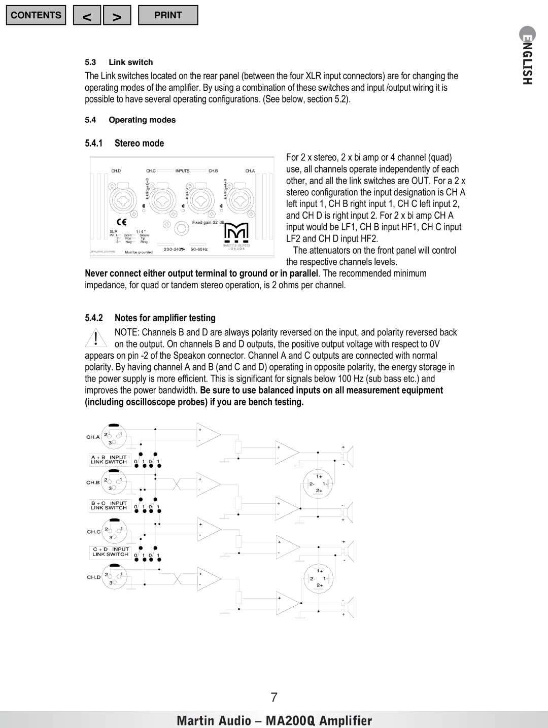
For 2 x stereo, 2 x bi amp or 4 channel (quad)


CH.D


CH.C


INPUTS


CH.B


CH.A

use, all channels operate independently of each


e C+ D


eA+B


other, and all the link switches are OUT. For a 2 x


g


kB+ C


g


stereo configuration the input designation is CH A


/k Brid


/kBrid


iLn


iLn


iLn


left input 1, CH B right input 1, CH C left input 2,


and CH D is right input 2. For 2 x bi amp CH A


Fixed gain 32 dB


XLR


1/ 4 “


input would be LF1, CH B input HF1, CH C input


Pin 1


Scrn

Sleeve


LF2 and CH D input HF2.


2


Pos


Tip


3


Neg


Ring


The attenuators on the front panel will control


Must be grounded


230-240V 50-60Hz


the respective channels levels.

Never connect either output terminal to ground or in parallel. The recommended minimum impedance, for quad or tandem stereo operation, is 2 ohms per channel.

5.4.2Notes for amplifier testing

!NOTE: Channels B and D are always polarity reversed on the input, and polarity reversed back on the output. On channels B and D outputs, the positive output voltage with respect to 0V

appears on pin -2 of the Speakon connector. Channel A and C outputs are connected with normal polarity. By having channel A and B (and C and D) operating in opposite polarity, the energy storage in the power supply is more efficient. This is significant for signals below 100 Hz (sub bass etc.) and improves the power bandwidth. Be sure to use balanced inputs on all measurement equipment (including oscilloscope probes) if you are bench testing.

7

Martin Audio – MA200Q Amplifier

ENGLISH

Page 7
Image 7
Martin Audio MA200Q important safety instructions Stereo mode

MA200Q specifications

The Martin Audio MA200Q is a versatile, high-performance amplifier designed to meet the demands of various professional audio applications. Known for its reliability and sound quality, the MA200Q is particularly suited for larger venues, touring, and installations where power and audio fidelity are paramount.

One of the standout features of the MA200Q is its four-channel architecture, which provides flexibility and efficiency. Each channel is capable of delivering 200 watts at 4 ohms, allowing users to drive multiple speakers or configurations easily. The amplifier also boasts a bridged mode, enabling users to combine channels for increased output, which is ideal for larger sound systems.

The MA200Q incorporates advanced Class D amplifier technology, which not only enhances audio quality but also improves energy efficiency. This technology significantly reduces heat generation, allowing the amplifier to operate cool and quietly, even during demanding performances. This means that users can rely on the MA200Q for extended periods without worrying about overheating or performance degradation.

Another notable feature is the comprehensive protection circuitry integrated into the amplifier. This includes short circuit protection, thermal protection, and limiting functions to safeguard both the amplifier and connected speakers from damage. The result is a robust and durable amplifier that ensures longevity in both touring and fixed installations.

In terms of connectivity, the Martin Audio MA200Q offers balanced XLR inputs and both speakON and binding post outputs, providing compatibility with a wide range of sound systems and setups. Its user-friendly design allows for easy adjustments and monitoring, with signal and clip indicators for each channel.

Moreover, the amplifier's compact and lightweight design makes it highly portable, a significant advantage for touring professionals. Even with these features, the MA200Q maintains a manageable weight, allowing for hassle-free transport and installation.

Overall, the Martin Audio MA200Q stands out in the marketplace for its combination of power, efficiency, and reliability. Whether used in live sound reinforcement, permanent installations, or corporate events, the MA200Q delivers a high-quality audio experience that professionals can trust. With features designed to enhance performance while ensuring durability, it remains a go-to choice for those seeking an exceptional amplification solution.