Location Requirements

WARNING

Explosion Hazard

Keep flammable materials and vapors, such as gasoline, away from refrigerator.

Failure to do so can result in death, explosion, or fire.

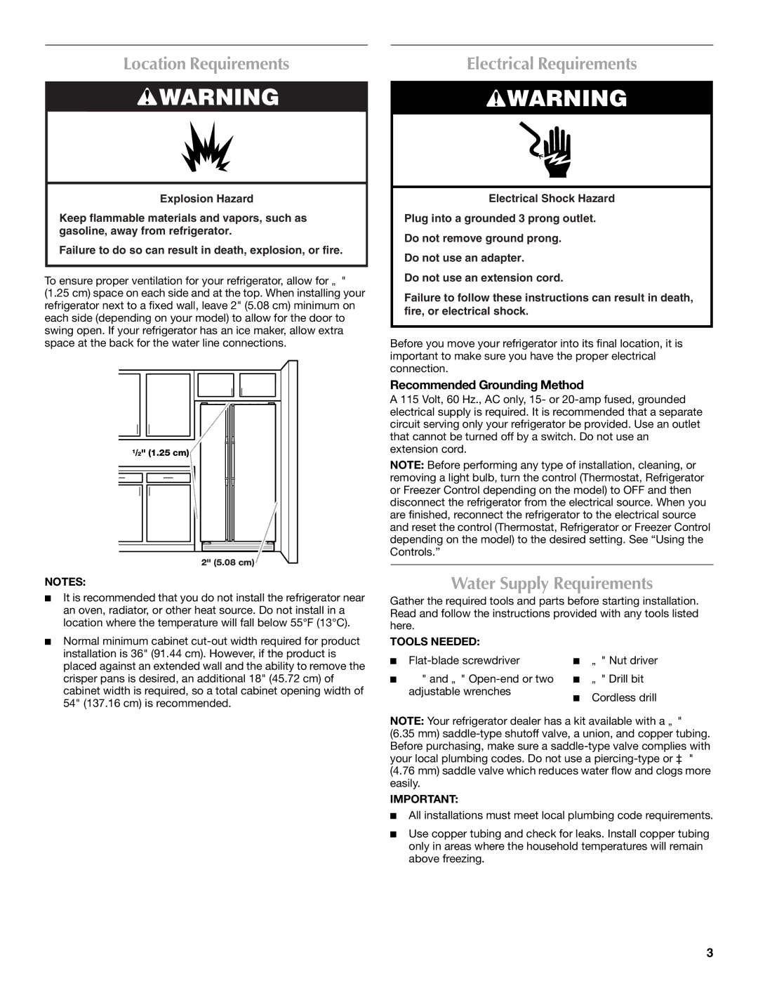
To ensure proper ventilation for your refrigerator, allow for ¹⁄₂" (1.25 cm) space on each side and at the top. When installing your refrigerator next to a fixed wall, leave 2" (5.08 cm) minimum on each side (depending on your model) to allow for the door to swing open. If your refrigerator has an ice maker, allow extra space at the back for the water line connections.

1/2" (1.25 cm)

2" (5.08 cm)

NOTES:

It is recommended that you do not install the refrigerator near an oven, radiator, or other heat source. Do not install in a location where the temperature will fall below 55°F (13°C).

Normal minimum cabinet cut-out width required for product installation is 36" (91.44 cm). However, if the product is placed against an extended wall and the ability to remove the crisper pans is desired, an additional 18" (45.72 cm) of cabinet width is required, so a total cabinet opening width of 54" (137.16 cm) is recommended.

Electrical Requirements

WARNING

Electrical Shock Hazard

Plug into a grounded 3 prong outlet.

Do not remove ground prong.

Do not use an adapter.

Do not use an extension cord.

Failure to follow these instructions can result in death, fire, or electrical shock.

Before you move your refrigerator into its final location, it is important to make sure you have the proper electrical connection.

Recommended Grounding Method

A 115 Volt, 60 Hz., AC only, 15- or 20-amp fused, grounded electrical supply is required. It is recommended that a separate circuit serving only your refrigerator be provided. Use an outlet that cannot be turned off by a switch. Do not use an extension cord.

NOTE: Before performing any type of installation, cleaning, or removing a light bulb, turn the control (Thermostat, Refrigerator or Freezer Control depending on the model) to OFF and then disconnect the refrigerator from the electrical source. When you are finished, reconnect the refrigerator to the electrical source and reset the control (Thermostat, Refrigerator or Freezer Control depending on the model) to the desired setting. See “Using the Controls.”

Water Supply Requirements

Gather the required tools and parts before starting installation. Read and follow the instructions provided with any tools listed here.

TOOLS NEEDED:

Flat-blade screwdriver

¹⁄₄" Nut driver

⁷⁄₁₆" and ¹⁄₂" Open-end or two

¹⁄₄" Drill bit


adjustable wrenches

Cordless drill


NOTE: Your refrigerator dealer has a kit available with a ¹⁄₄"

(6.35 mm) saddle-type shutoff valve, a union, and copper tubing. Before purchasing, make sure a saddle-type valve complies with your local plumbing codes. Do not use a piercing-type or ³⁄₁₆"

(4.76 mm) saddle valve which reduces water flow and clogs more easily.

IMPORTANT:

All installations must meet local plumbing code requirements.

Use copper tubing and check for leaks. Install copper tubing only in areas where the household temperatures will remain above freezing.

3

Page 3
Image 3
Maytag W10214489A Location Requirements, Electrical Requirements, Water Supply Requirements, Recommended Grounding Method

W10214488A, W10214489A specifications

The Maytag W10214488A and W10214489A are essential components in modern kitchen appliances, particularly designed for Maytag dishwashers. These parts are not just replacements; they embody the brand’s commitment to ultimate performance, reliability, and user convenience, making them an integral part of the dishwashing ecosystem.

The W10214488A, often recognized as a lower spray arm, works diligently at the base of the dishwasher to ensure that water is efficiently distributed throughout the machine. Its innovative design allows it to reach every corner of the dishwasher, guaranteeing thorough cleaning of dishes, pots, and pans. This feature reduces the chance of residual food particles being left behind, which can lead to unpleasant odors and hygiene concerns.

In contrast, the W10214489A serves as the upper spray arm, designed to complement its counterpart’s performance. It utilizes advanced spray technology that generates a consistent and powerful stream of water, ensuring effective cleaning for items placed in the upper rack. This design is particularly beneficial for delicate glassware and smaller items, giving users the peace of mind that even the most fragile dishes will come out spotless and undamaged.

Both parts are crafted from high-quality materials, designed to withstand the rigorous demands of frequent use while maintaining their shape and functionality. They are engineered for easy installation, allowing homeowners to quickly replace old or malfunctioning components without the need for professional assistance. This user-friendly approach aligns with Maytag’s reputation for durability and serviceability.

Moreover, these spray arms are engineered to promote water efficiency, an essential feature in today’s environmentally conscious world. By optimizing water usage, Maytag’s designs contribute to lower utility bills while ensuring the same high-quality cleaning performance.

In essence, Maytag’s W10214488A and W10214489A embody the brand’s dedication to producing reliable, efficient, and effective home appliances. With their advanced features and user-friendly design, these components offer a solution for maintaining the cleanliness of every meal's aftermath, ensuring that users can trust their dishwasher to deliver exceptional results every time. These parts enhance the overall performance of Maytag dishwashers, ensuring that the brand remains synonymous with quality and innovation in the realm of kitchen appliances.