Installation
Installing the Loudspeaker, con’t
6.Prepare the Loudspeaker hookup cables by carefully re- move sufficient insulation from the cable ends and twist the strands together, refer to figures 9, 10 & 11.
Note: If desired, the twisted ends can be tinned with solder to keep the strands together.
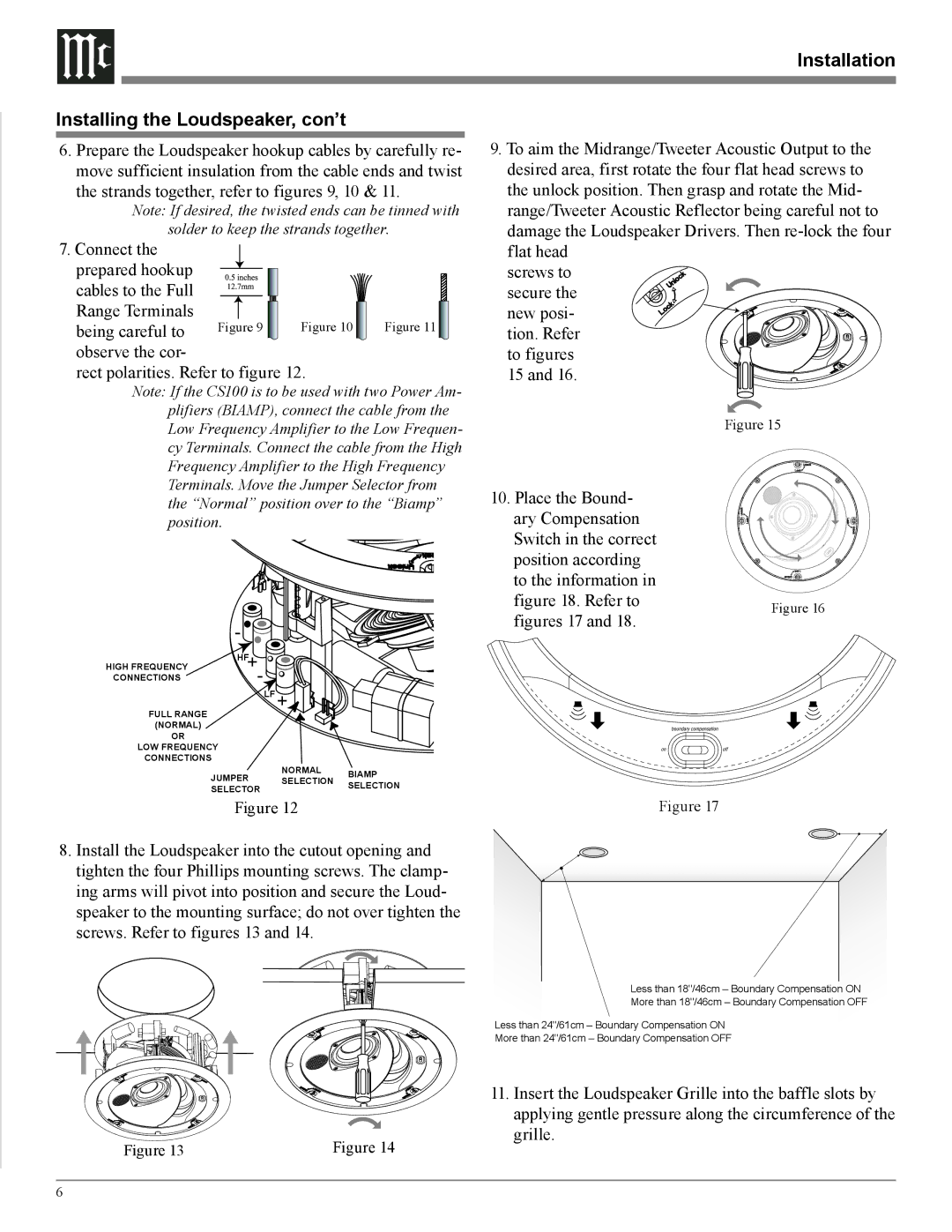
7.Connect the
prepared hookup |
|
|
|
cables to the Full |
|
|
|
Range Terminals | Figure 9 | Figure 10 | Figure 11 |
being careful to | |||
observe the cor- |
|
|
|
rect polarities. Refer to figure 12.
Note: If the CS100 is to be used with two Power Am- plifiers (BIAMP), connect the cable from the Low Frequency Amplifier to the Low Frequen- cy Terminals. Connect the cable from the High Frequency Amplifier to the High Frequency Terminals. Move the Jumper Selector from the “Normal” position over to the “Biamp” position.
![]() -
- ![]()
![]()
![]()
![]()
![]()
![]()
![]()
![]()
![]()
![]()
![]()
![]()
![]()
![]()
HIGH FREQUENCY | HF+ |
CONNECTIONS | - |
LF +
FULL RANGE
(NORMAL)
OR
LOW FREQUENCY
CONNECTIONS
JUMPER NORMAL BIAMP
SELECTOR SELECTION SELECTION
Figure 12
9.To aim the Midrange/Tweeter Acoustic Output to the desired area, first rotate the four flat head screws to
the unlock position. Then grasp and rotate the Mid- range/Tweeter Acoustic Reflector being careful not to damage the Loudspeaker Drivers. Then
screws to
secure the
new posi- tion. Refer to figures 15 and 16.
Figure 15
10. Place the Bound- |
| |
ary Compensation |
| |
Switch in the correct |
| |
position according |
| |
to the information in |
| |
figure 18. Refer to | Figure 16 | |
figures 17 and 18. | ||
|
Figure 17
8. Install the Loudspeaker into the cutout opening and tighten the four Phillips mounting screws. The clamp- ing arms will pivot into position and secure the Loud- speaker to the mounting surface; do not over tighten the screws. Refer to figures 13 and 14.
Less than 18"/46cm – Boundary Compensation ON
More than 18"/46cm – Boundary Compensation OFF
Less than 24"/61cm – Boundary Compensation ON
More than 24"/61cm – Boundary Compensation OFF
11. Insert the Loudspeaker Grille into the baffle slots by
|
| applying gentle pressure along the circumference of the |
Figure 13 | Figure 14 | grille. |
|
6