How to Connect the MC602
|
|
|
|
|
|
|
|
|
|
|
|
|
|
|
|
|
| Banana plug connection: | |
Caution: The supplied AC Power Cord should not be |
|
|
| ||||||||||||||||
connected to the Rear Panel of the MC602 |
|
|
| Insert the banana plug into the hole at the top of the | |||||||||||||||
Amplifier until after the Loudspeaker Connections | terminal. Tighten the top portion of the terminal post | ||||||||||||||||||
have been made and the supplied protective |
|
|
| and the set screw to secure the banana plug in place. | |||||||||||||||
Terminal Connections Cover has been installed. | Note: The use of Banana Plugs is for use in the United | ||||||||||||||||||
Failure to observe this could result in Electric | |||||||||||||||||||
States and Canada only. | |||||||||||||||||||
Shock. |
|
|
| ||||||||||||||||
|
|
| 4. Connect the loudspeaker hookup cables to the output | ||||||||||||||||
1. For Remote Power Control, connect a power control | |||||||||||||||||||
terminals that match the impedance of your loudspeak- | |||||||||||||||||||
cable from the Control Center or Preamplifier Power | |||||||||||||||||||
ers, being careful to observe the correct polarities. Out- | |||||||||||||||||||
Control Out to the MC602 Power Control In. |
|
|
| ||||||||||||||||
|
|
| put impedance connections of 2 ohms, 4 ohms and 8 | ||||||||||||||||
2. Connect cables from the Balanced Outputs of a McIn- | |||||||||||||||||||
ohms are provided. If the impedance of your loud- | |||||||||||||||||||
tosh Preamplifier or Control Center to the MC602 Bal- | |||||||||||||||||||
speakers is | |||||||||||||||||||
anced Inputs. |
|
|
| ||||||||||||||||
|
|
| the nearest lower impedance connection. | ||||||||||||||||
Note: An optional hookup is to use unbalanced cables. | |||||||||||||||||||
WARNING: Loudspeaker terminals are hazardous live | |||||||||||||||||||
3. Prepare the Loudspeaker Hookup Cables that attach to | |||||||||||||||||||
and present a risk of electric shock. For | |||||||||||||||||||
the MC602 Power Amplifier by choosing one of the | |||||||||||||||||||
additional instruction on making | |||||||||||||||||||
methods below: |
|
|
| Loudspeaker Connections contact your | |||||||||||||||
Bare wire cable ends: |
|
|
| McIntosh Dealer or McIntosh Technical | |||||||||||||||
Carefully remove sufficient insulation from the cable | Support. | ||||||||||||||||||
ends, refer to figures 1, |
|
|
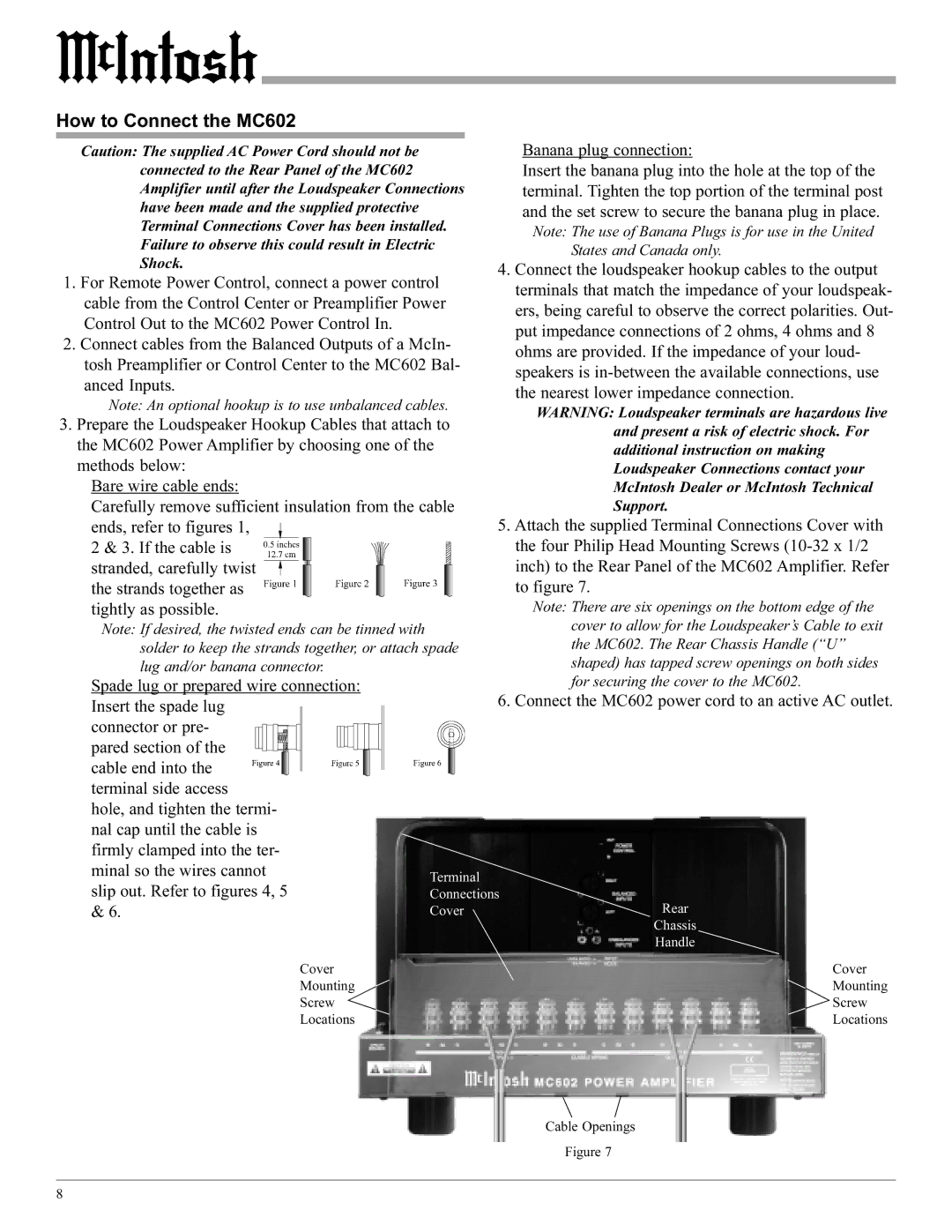
| 5. Attach the supplied Terminal Connections Cover with | |||||||||||||||
2 & 3. If the cable is |
|
|
|
|
|
| the four Philip Head Mounting Screws | ||||||||||||
|
|
|
|
|
|
|
|
|
|
|
|
|
|
| |||||
stranded, carefully twist |
|
|
|
|
|
|
|
| inch) to the Rear Panel of the MC602 Amplifier. Refer | ||||||||||
|
|
|
|
|
|
|
|
|
|
|
|
|
|
| |||||
|
|
|
|
|
|
| |||||||||||||
|
|
|
|
|
|
| |||||||||||||
|
|
|
|
| |||||||||||||||
the strands together as |
|
|
|
|
|
|
| to figure 7. | |||||||||||
tightly as possible. |
|
|
| Note: There are six openings on the bottom edge of the | |||||||||||||||
Note: If desired, the twisted ends can be tinned with |
|
|
| cover to allow for the Loudspeaker’s Cable to exit | |||||||||||||||
solder to keep the strands together, or attach spade | the MC602. The Rear Chassis Handle (“U” | ||||||||||||||||||
lug and/or banana connector. |
|
|
| shaped) has tapped screw openings on both sides | |||||||||||||||
Spade lug or prepared wire connection: |
|
|
| for securing the cover to the MC602. | |||||||||||||||
Insert the spade lug |
|
|
| 6. Connect the MC602 power cord to an active AC outlet. | |||||||||||||||
|
|
|
| ||||||||||||||||
connector or pre- |
|
|
|
|
|
|
|
|
|
|
|
|
| ||||||
|
|
|
|
|
|
|
|
|
|
|
|
| |||||||
pared section of the |
|
|
|
|
|
|
|
|
|
|
|
|
|
|
|
|
|
| |
|
|
|
|
|
|
|
|
|
|
|
|
| |||||||
|
|
|
|
|
|
|
|
|
|
|
|
|
|
|
|
|
| ||
cable end into the |
|
|
|
|
|
|
|
|
|
|
|
| |||||||
terminal side access |
|
|
|
| |||||||||||||||
hole, and tighten the termi- |
|
|
|
| |||||||||||||||
nal cap until the cable is |
|
|
|
| |||||||||||||||
firmly clamped into the ter- |
|
|
|
| |||||||||||||||
minal so the wires cannot | Terminal |
| |||||||||||||||||
slip out. Refer to figures 4, 5 |
| ||||||||||||||||||
Connections | |||||||||||||||||||
& 6. |
|
|
|
|
|
|
|
|
|
|
|
|
|
| Cover | Rear | |||
|
|
|
|
|
|
|
|
|
|
|
|
|
|
|
|
|
| Chassis | |
|
|
|
|
|
|
|
|
|
|
|
|
|
|
|
|
|
| Handle | |
|
| Cover |
|
|
| Cover | |||||||||||||
|
| Mounting |
|
|
| Mounting | |||||||||||||
|
| Screw |
|
|
| Screw | |||||||||||||
|
| Locations |
|
|
| Locations | |||||||||||||
Cable Openings
Figure 7
8