XRT30 specifications
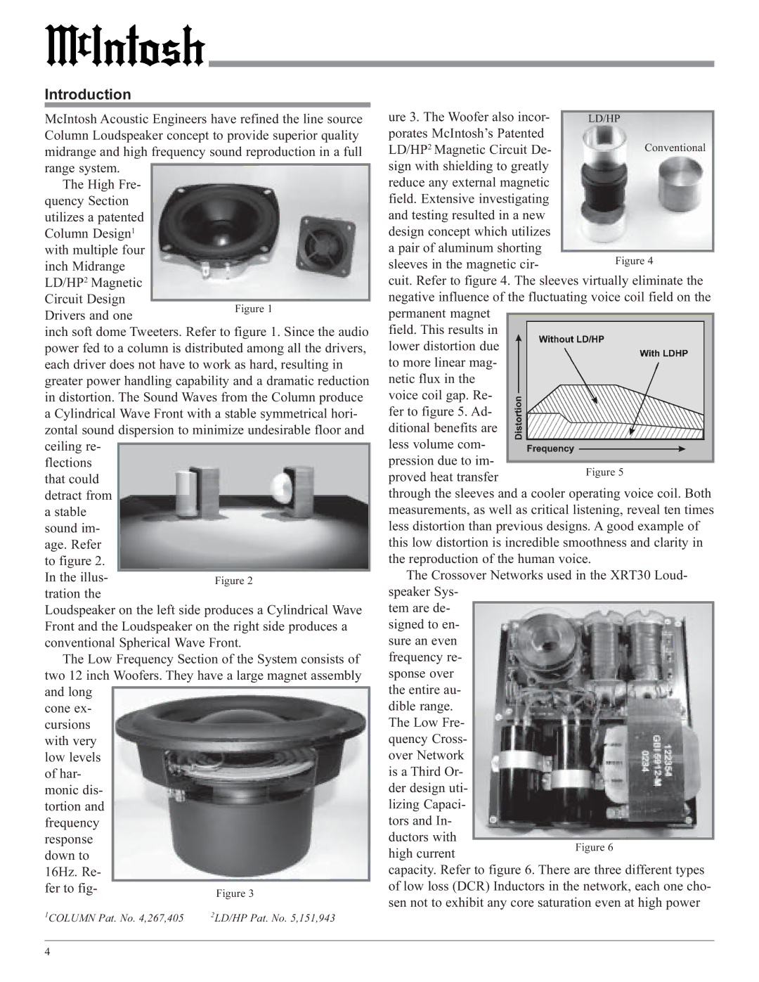
The McIntosh XRT30 is a remarkable loudspeaker that embodies the high standards of audio engineering synonymous with the McIntosh brand. Renowned for its advanced technology and exceptional performance, the XRT30 provides a listening experience that caters to audiophiles and music enthusiasts alike.One of the standout features of the XRT30 is its unique design, which includes a slender, elegant cabinet that minimizes the distortion commonly associated with conventional loudspeakers. This innovative design helps to achieve a more accurate sound reproduction, ensuring that each note is rendered with striking clarity and precision.
The speaker utilizes a proprietary driver array that combines several advanced technologies. The high-frequency section consists of specially designed silk-dome tweeters that provide a smooth and extended response, reaching frequencies up to 40 kHz. This makes for crystal-clear highs that bring out the most intricate details in any recording.
In addition to the high-frequency drivers, the XRT30 is equipped with several midrange drivers arranged in a unique configuration. This array is engineered to create a broad soundstage, allowing listeners to feel immersed in the music. The midrange drivers are vital for delivering the warmth and presence of vocals and acoustic instruments, ensuring that every performance feels dynamic and engaging.
The low-frequency performance of the XRT30 is powered by dual 12-inch woofers. These woofers are optimized for deep bass response and are housed in a carefully calibrated enclosure that enhances their performance. The result is a robust low-end that remains tight and controlled, even at high volume levels.
Overall, the XRT30 is designed to handle high power levels without distortion, thanks to its robust construction and high-efficiency drivers. Each speaker is hand-crafted, reflecting McIntosh’s commitment to excellence in both sound quality and build quality.
With its elegant finish, the XRT30 adds a touch of sophistication to any listening space. The combination of advanced design, quality materials, and meticulous craftsmanship make it a worthy addition to any high-end audio system. For those who seek an unparalleled listening experience, the McIntosh XRT30 presents a compelling option that delivers on both performance and aesthetic appeal.

