The optical tube has been pre-drilled at the Meade factory to accept all standard accessories.
1.Attaching the Focuser: Lay the tube flat on the floor. Align the holes in the focuser assembly (1, Fig. 1) with the four pre-drilled holes in the optical tube. From the provided hardware, place the four Phillips-head screws through the holes. Then, carefully reach into the optical tube and attach a nut and washer to each screw. Tighten the screws, but do not overtighten; tightening to a firm feel is sufficient.
2.Attaching the Viewfinder: With the optical tube lying flat on the floor, align the two holes in the viewfinder bracket (3, Fig.1) with the pre-drilled holes in the optical tube. From the supplied hardware, place a screw through each of the holes. Carefully reach into the optical tube and attach a nut to each screw. As with the focuser, tightening to a firm feel is sufficient. Overtightening may result in damage to the tube's finish. Aligning the viewfinder is discussed later in this manual.
Your Meade Starfinder telescope was fully assembled, aligned, and tested at the Meade factory. To ensure safe shipping, the primary mirror was then removed from the telescope. Locate the primary mirror cell assembly (Fig 3). Again, take extreme care not to touch or bump the primary mirror.
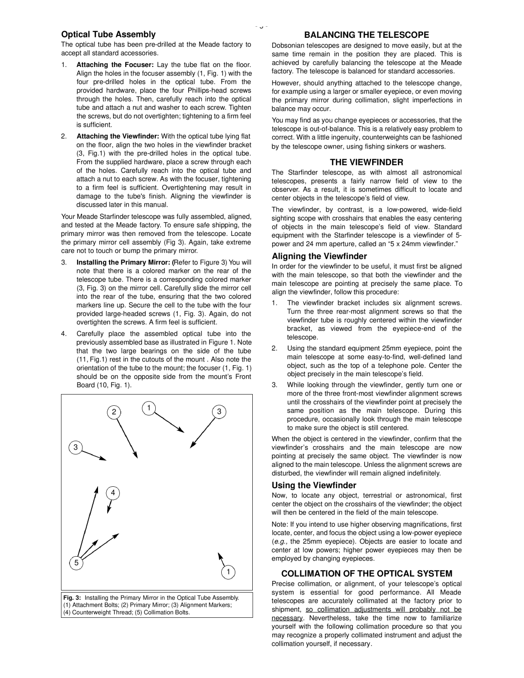
3.Installing the Primary Mirror: (Refer to Figure 3) You will note that there is a colored marker on the rear of the telescope tube. There is a corresponding colored marker (3, Fig. 3) on the mirror cell. Carefully slide the mirror cell into the rear of the tube, ensuring that the two colored markers line up. Secure the cell to the tube with the four provided large-headed screws (1, Fig. 3). Again, do not overtighten the screws. A firm feel is sufficient.
4.Carefully place the assembled optical tube into the previously assembled base as illustrated in Figure 1. Note that the two large bearings on the side of the tube (11, Fig.1) rest in the cutouts of the mount . Also note the orientation of the tube to the mount; the focuser (1, Fig. 1) should be on the opposite side from the mount’s Front Board (10, Fig. 1).
1
23
3
4
5
1
Fig. 3: Installing the Primary Mirror in the Optical Tube Assembly.
(1)Attachment Bolts; (2) Primary Mirror; (3) Alignment Markers;
(4)Counterweight Thread; (5) Collimation Bolts.
Dobsonian telescopes are designed to move easily, but at the same time remain in the position they are placed. This is achieved by carefully balancing the telescope at the Meade factory. The telescope is balanced for standard accessories.
However, should anything attached to the telescope change, for example using a larger or smaller eyepiece, or even moving the primary mirror during collimation, slight imperfections in balance may occur.
You may find as you change eyepieces or accessories, that the telescope is out-of-balance. This is a relatively easy problem to correct. With a little ingenuity, counterweights can be fashioned by the telescope owner, using fishing sinkers or washers.
THE VIEWFINDER
The Starfinder telescope, as with almost all astronomical telescopes, presents a fairly narrow field of view to the observer. As a result, it is sometimes difficult to locate and center objects in the telescope’s field of view.
The viewfinder, by contrast, is a low-powered, wide-field sighting scope with crosshairs that enables the easy centering of objects in the main telescope’s field of view. Standard equipment with the Starfinder telescope is a viewfinder of 5- power and 24 mm aperture, called an “5 x 24mm viewfinder.”
Aligning the Viewfinder
In order for the viewfinder to be useful, it must first be aligned with the main telescope, so that both the viewfinder and the main telescope are pointing at precisely the same place. To align the viewfinder, follow this procedure:
1.The viewfinder bracket includes six alignment screws. Turn the three rear-most alignment screws so that the viewfinder tube is roughly centered within the viewfinder bracket, as viewed from the eyepiece-end of the telescope.
2.Using the standard equipment 25mm eyepiece, point the main telescope at some easy-to-find, well-defined land object, such as the top of a telephone pole. Center the object precisely in the main telescope’s field.
3.While looking through the viewfinder, gently turn one or more of the three front-most viewfinder alignment screws until the crosshairs of the viewfinder point at precisely the same position as the main telescope. During this procedure, occasionally look through the main telescope to make sure the object is still centered.
When the object is centered in the viewfinder, confirm that the viewfinder’s crosshairs and the main telescope are now pointing at precisely the same object. The viewfinder is now aligned to the main telescope. Unless the alignment screws are disturbed, the viewfinder will remain aligned indefinitely.
Using the Viewfinder
Now, to locate any object, terrestrial or astronomical, first center the object on the crosshairs of the viewfinder; the object will then be centered in the field of the main telescope.
Note: If you intend to use higher observing magnifications, first locate, center, and focus the object using a low-power eyepiece (e.g., the 25mm eyepiece). Objects are easier to locate and center at low powers; higher power eyepieces may then be employed by changing eyepieces.
COLLIMATION OF THE OPTICAL SYSTEM
Precise collimation, or alignment, of your telescope’s optical system is essential for good performance. All Meade telescopes are accurately collimated at the factory prior to shipment, so collimation adjustments will probably not be necessary. Nevertheless, take the time now to familiarize yourself with the following collimation procedure so that you may recognize a properly collimated instrument and adjust the collimation yourself, if necessary.