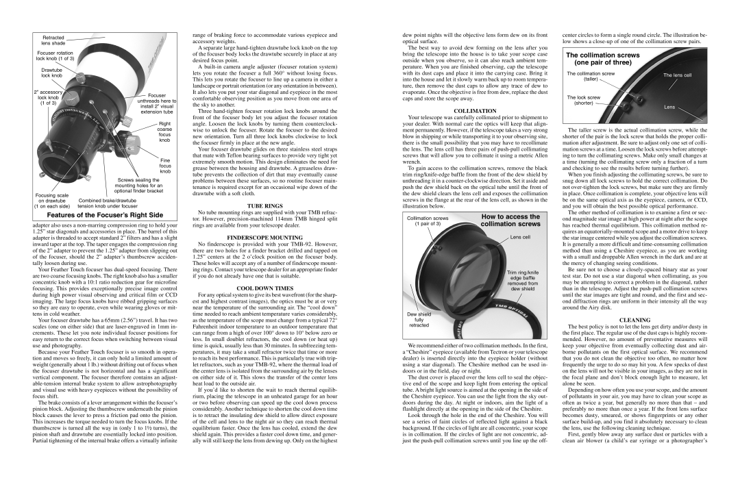
Retracted  lens shade
Focuser rotation lock knob (1 of 3)
Drawtube lock knob
| 2” accessory | Focuser |
| lock knob |
| unthreads here to |
| (1 of 3) |
| install 2” visual |
| |
| | extension tube |
| | Right |
| | coarse |
| | focus |
| | knob |
| | Fine |
| | focus |
| | knob |
| | Screws sealing the |
| | mounting holes for an |
| Focusing scale | optional finder bracket |
| Combined brake/drawtube |
| on drawtube |
(1 on each side) tension knob under focuser
Features of the Focuser’s Right Side
adapter also uses a non-marring compression ring to hold your 1.25” star diagonals and accessories in place. The barrel of this adapter is threaded to accept standard 2” filters and has a slight inward taper at the top. The taper engages the compression ring of the 2” adapter to prevent the 1.25” adapter from slipping out of the focuser, should the 2” adapter’s thumbscrew acciden- tally loosen during use.
Your Feather Touch focuser has dual-speed focusing. There are two coarse focusing knobs. The right knob also has a smaller concentric knob with a 10:1 ratio reduction gear for microfine focusing. This provides exceptionally precise image control during high power visual observing and critical film or CCD imaging. The large focus knobs have ribbed gripping surfaces so they are easy to operate, even while wearing gloves or mit- tens in cold weather.
Your focuser drawtube has a 65mm (2.56”) travel. It has two scales (one on either side) that are laser-engraved in 1mm in- crements. These let you note individual focuser positions for easy return to the correct focus when switching between visual use and photography.
Because your Feather Touch focuser is so smooth in opera- tion and moves so freely, it can only hold a limited amount of weight (generally about 1 lb.) without drifting out of focus when the focuser drawtube is not horizontal and has a significant vertical component. The focuser therefore contains an adjust- able-tension internal brake system to allow astrophotography and visual use with heavy eyepieces without the possibility of focus shift.
The brake consists of a lever arrangement within the focuser’s pinion block. Adjusting the thumbscrew underneath the pinion block causes the lever to press a friction pad onto the pinion. This increases the torque needed to turn the focus knobs. If the thumbscrew is turned all the way in (only 1 to 1½ turns), the pinion shaft and drawtube are essentially locked into position. Partial tightening of the internal brake offers a virtually infinite
range of braking force to accommodate various eyepiece and accessory weights.
A separate large hand-tighten drawtube lock knob on the top of the focuser body locks the drawtube securely in place at any desired focus point.
Abuilt-in camera angle adjuster (focuser rotation system) lets you rotate the focuser a full 360° without losing focus. This lets you rotate the focuser to line up a camera in either a landscape or portrait orientation (or any orientation in between). It also lets you put your star diagonal and eyepiece in the most comfortable observing position as you move from one area of the sky to another.
Three hand-tighten focuser rotation lock knobs around the front of the focuser body let you adjust the focuser rotation angle. Loosen the lock knobs by turning them counterclock- wise to unlock the focuser. Rotate the focuser to the desired new orientation. Turn all three lock knobs clockwise to lock the focuser firmly in place at the new angle.
Your focuser drawtube glides on three stainless steel straps that mate with Teflon bearing surfaces to provide very tight yet extremely smooth motion. This design eliminates the need for grease between the housing and drawtube. A greaseless draw- tube prevents the collection of dirt that may eventually cause problems between these surfaces, so no routine focuser main- tenance is required except for an occasional wipe down of the drawtube with a soft cloth.
TUBE RINGS
No tube mounting rings are supplied with your TMB refrac- tor. However, precision-machined 114mm TMB hinged split rings are available from your telescope dealer.
FINDERSCOPE MOUNTING
No finderscope is provided with your TMB-92. However, there are two holes for a finder bracket drilled and tapped on 1.25” centers at the 2 o’clock position on the focuser body. These holes will accept any of a number of finderscope mount- ing rings. Contact your telescope dealer for an appropriate finder if you do not already have one that is suitable.
COOL DOWN TIMES
For any optical system to give its best wavefront (for the sharp- est and highest contrast images), the optics must be at or very near the temperature of the surrounding air. The “cool down” time needed to reach ambient temperature varies considerably, as the temperature of the scope must change from a typical 72° Fahrenheit indoor temperature to an outdoor temperature that can range from a high of over 100° down to 10° below zero or less. In small doublet refractors, the cool down (or heat up) time is quick, usually less than 30 minutes. In subfreezing tem- peratures, it may take a small refractor twice that time or more to reach its best performance. This is particularly true with trip- let refractors, such as your TMB-92, where the thermal load of the center lens is isolated from the surrounding air by the lenses on either side of it. This slows the transfer of the center lens heat load to the outside air.
If you’d like to shorten the wait to reach thermal equilib- rium, placing the telescope in an unheated garage for an hour or two before observing can speed up the cool down process considerably. Another technique to shorten the cool down time is to retract the insulating dew shield to allow direct exposure of the cell and lens to the night air so they can reach thermal equilibrium faster. Once the lens has cooled, extend the dew shield again. This provides a faster cool down time, and gener- ally will still keep the lens from dewing up. Only on the highest
dew point nights will the objective lens form dew on its front optical surface.
The best way to avoid dew forming on the lens after you bring the telescope into the house is to take your scope case outside when you observe, so it can also reach ambient tem- perature. When you are finished observing, cap the telescope with its dust caps and place it into the carrying case. Bring it into the house and let it slowly warm back up to room tempera- ture, then remove the dust caps to allow any trace of dew to evaporate. Once the objective is free from dew, replace the dust caps and store the scope away.
COLLIMATION
Your telescope was carefully collimated prior to shipment to your dealer. With normal care the optics will keep that align- ment permanently. However, if the telescope takes a very strong blow in shipping or while transporting it to your observing site, there is the small possibility that you may have to recollimate the lens. The lens cell has three pairs of push-pull collimating screws that will allow you to collimate it using a metric Allen wrench.
To gain access to the collimation screws, remove the black trim ring/knife-edge baffle from the front of the dew shield by unthreading it in a counter-clockwise direction. Set it aside and push the dew shield back on the optical tube until the front of the dew shield clears the lens cell and exposes the collimation screws in the flange at the rear of the lens cell, as shown in the illustration below.
Collimation screws | How to access the |
(1 pair of 3) | collimation screws |
| Lens cell |
Trim ring /knife
edge baffle
removed from
dew shield
Dew shield
fully
retracted
We recommend either of two collimation methods. In the first, a “Cheshire” eyepiece (available from Tectron or your telescope dealer) is inserted directly into the eyepiece holder (without using a star diagonal). The Cheshire method can be used in- doors or in the field, day or night.
The dust cover is placed over the lens cell to seal the objec- tive end of the scope and keep light from entering the optical tube. A bright light source is aimed at the opening in the side of the Cheshire eyepiece. You can use the light from the sky out- doors during the day. At night or indoors, aim the light of a flashlight directly at the opening in the side of the Cheshire.
Look through the hole in the end of the Cheshire. You will see a series of faint circles of reflected light against a black background. If the circles of light are all concentric, your scope is in collimation. If the circles of light are not concentric, ad- just the push-pull collimation screws until you line up the off-
center circles to form a single round circle. The illustration be- low shows a close-up of one of the collimation screw pairs.
The collimation screws
(one pair of three)
| The collimation screw | The lens cell |
| (taller) |
| |
| The lock screw | |
| (shorter) | Lens |
| |
The taller screw is the actual collimation screw, while the shorter of the pair is the lock screw that holds the proper colli- mation after adjustment. Be sure to adjust only one set of colli- mation screws at a time. Loosen the lock screws before attempt- ing to turn the collimating screws. Make only small changes at a time (turning the collimating screw only a fraction of a turn and checking to see the results before turning further).
When you finish adjusting the collimating screws, be sure to snug down all lock screws to hold the correct collimation. Do not over-tighten the lock screws, but make sure they are firmly in place. Once collimation is complete, your objective lens will be on the same optical axis as the eyepiece, camera, or CCD, and you will obtain the best possible optical performance.
The other method of collimation is to examine a first or sec- ond magnitude star image at high power at night after the scope has reached thermal equilibrium. This collimation method re- quires an equatorially-mounted scope and a motor drive to keep the star image centered while you adjust the collimation screws. It is generally a more difficult and time-consuming collimation method than using a Cheshire eyepiece, as you are working with a small and droppable Allen wrench in the dark and are at the mercy of changing seeing conditions.
Be sure not to choose a closely-spaced binary star as your test star. Do not use a star diagonal when collimating, as you may be attempting to correct a problem in the diagonal, rather than in the telescope. Adjust the push-pull collimation screws until the star images are tight and round, and the first and sec- ond diffraction rings are uniform in their intensity all the way around the Airy disk.
CLEANING
The best policy is not to let the lens get dirty and/or dusty in the first place. The regular use of the dust caps is highly recom- mended. However, no amount of preventative measures will keep your objective from eventually collecting dust and air- borne pollutants on the first optical surface. We recommend that you do not clean the objective too often, no matter how frequently the urge to do so may hit you. A few specks of dust on the lens will not be visible in your images, as they are not in the focal plane and don’t block enough light to measure, let alone be seen.
Depending on how often you use your scope, and the amount of pollutants in your air, you may have to clean your scope as often as twice a year, but generally no more than that – and preferably no more than once a year. If the front lens surface becomes dusty, smeared, or shows fingerprints or any other surface build-up, and you find it absolutely necessary to clean the lens, use the following cleaning technique.
First, gently blow away any surface dust or particles with a clean air blower (a child’s ear syringe or a photographer’s