Metra Electronics 
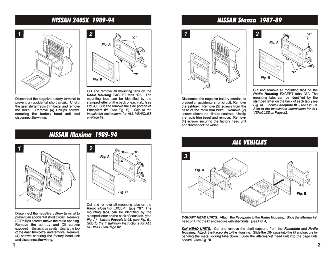
99-7407 Fig. A, Fig. B, NISSAN 240SX, NISSAN Stanza, NISSAN Maxima ALL VEHICLES

Models: 99-7407

1 2
Download 2 pages 42.95 Kb
Page 2
Image 2
NISSAN 240SX 1989-94

NISSAN 240SX 1989-94

NISSAN Stanza 1987-89

1

Disconnect the negative battery terminal to prevent an accidental short circuit. Unclip the gear shifter/radio trim bezel and remove the bezel. Remove (4) Phillips screws securing the factory head unit and disconnect the wiring.

2

"C"

Fig. A

"C"

Fig. B

Cut and remove all mounting tabs on the Radio Housing EXCEPT tabs "C". The mounting tabs can be identified by the stamped letter on the back of each tab. (see Fig. A). Cut and remove the side portion of Faceplate #1. (see Fig. B). Skip to the Installation Instructions for ALL VEHICLES on Page #2.

1

Disconnect the negative battery terminal to prevent an accidental short circuit. Remove the ashtray. Remove (2) screws from the base of the radio trim bezel. Remove (2) screws above the climate controls. Unclip the radio trim bezel and remove. Remove

(4)screws securing the factory head unit and disconnect the wiring.

2

"A"

Fig. A

"A"

Fig. B

Cut and remove all mounting tabs on the Radio Housing EXCEPT tabs "A". The mounting tabs can be identified by the stamped letter on the back of each tab. (see Fig. A). Locate Faceplate #1. (see Fig. B). Skip to the Installation Instructions for ALL VEHICLES on Page #2.

NISSAN Maxima 1989-94

ALL VEHICLES

1

Disconnect the negative battery terminal to prevent an accidental short circuit. Remove

(2)Phillips screws above the radio opening. Remove the ashtray and (2) screws exposed in the ashtray cavity. Unclip the top of the dash trim bezel and remove. Remove

(4)screws securing the factory head unit and disconnect the wiring.

1

2

"B"

Fig. A

Fig. B

Cut and remove all mounting tabs on the Radio Housing EXCEPT tabs "B". The mounting tabs can be identified by the stamped letter on the back of each tab. (see Fig. A). Locate Faceplate #2. (see Fig. B). Skip to the Installation Instructions for ALL VEHICLES on Page #2.

3

Fig. A

Fig. B

2-SHAFT HEAD UNITS: Attach the Faceplate to the Radio Housing. Slide the aftermarket head unit into the kit and secure with shaft nuts. (see Fig. A)

DIN HEAD UNITS: Cut and remove the shaft supports from the Faceplate and Radio Housing. Attach the Faceplate to the Housing. Slide the DIN cage into the kit and secure by bending the metal locking tabs down. Slide the aftermarket head unit into the cage until secure. (see Fig. B)

2

Page 2
Image 2
Metra Electronics 99-7407 NISSAN 240SX, NISSAN Stanza, NISSAN Maxima ALL VEHICLES, Fig. A Fig. B