4Connect to the Network
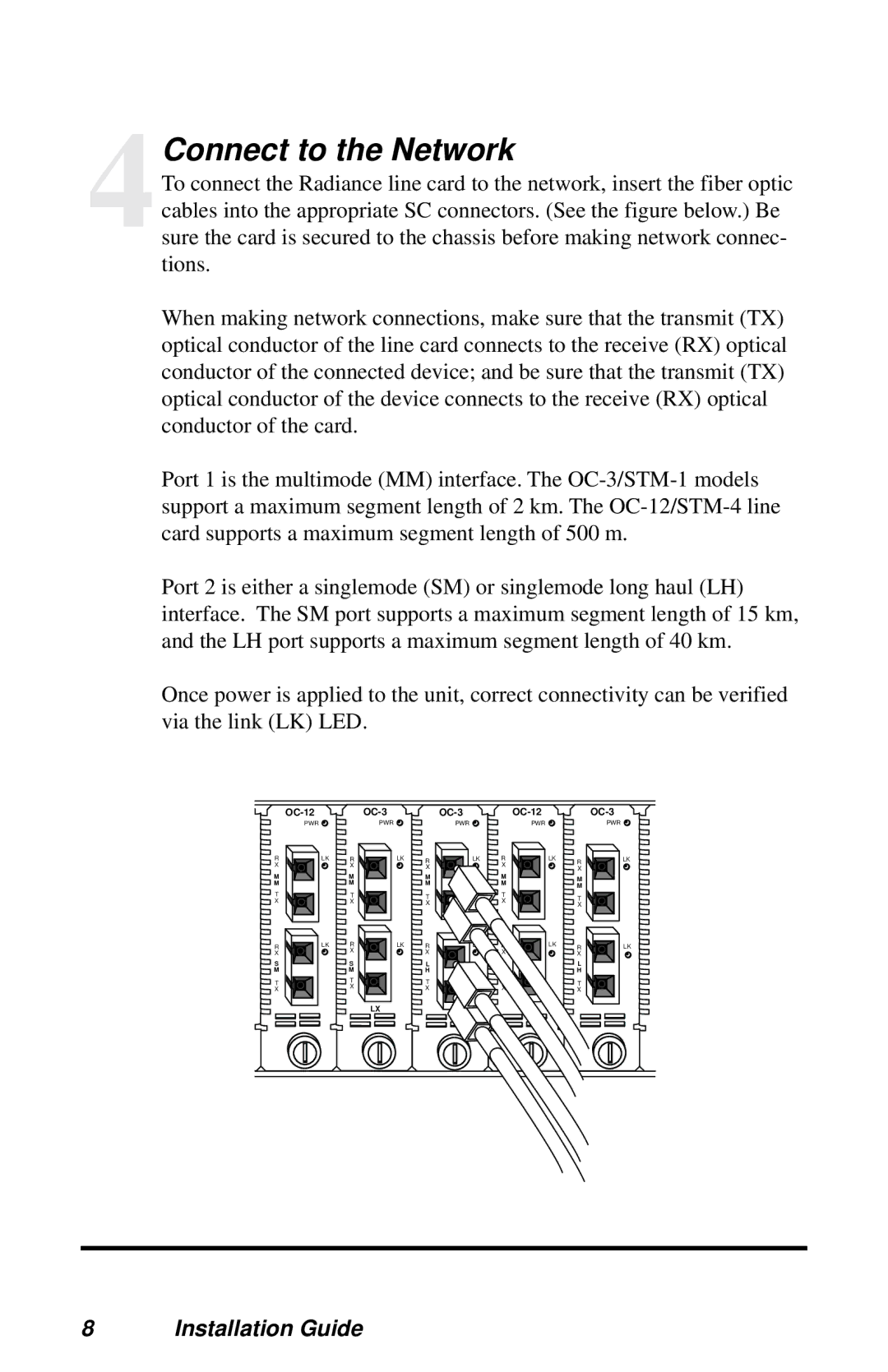
To connect the Radiance line card to the network, insert the fiber optic cables into the appropriate SC connectors. (See the figure below.) Be sure the card is secured to the chassis before making network connec- tions.
When making network connections, make sure that the transmit (TX) optical conductor of the line card connects to the receive (RX) optical conductor of the connected device; and be sure that the transmit (TX) optical conductor of the device connects to the receive (RX) optical conductor of the card.
Port 1 is the multimode (MM) interface. The
Port 2 is either a singlemode (SM) or singlemode long haul (LH) interface. The SM port supports a maximum segment length of 15 km, and the LH port supports a maximum segment length of 40 km.
Once power is applied to the unit, correct connectivity can be verified via the link (LK) LED.
PWR | PWR | PWR | PWR | PWR |
R X
M M
T X
R X
S
M
T X
LK | R | LK | R | LK | R | LK | R | LK |
| X |
| X |
| X |
| X |
|
|
|
|
|
|
|
| ||
| M |
| M |
| M |
| M |
|
| M |
| M |
| M |
|
| |
|
|
|
| M |
| |||
|
|
|
|
|
|
|
| |
| T |
| T |
| T |
| T |
|
| X |
|
| X |
|
| ||
|
| X |
|
| X |
| ||
|
|
|
|
|
|
|
LK | R | LK | R | LK | R | LK | R | LK |
| X |
| X |
| X |
| X |
|
| S |
| L |
| S |
| L |
|
| M |
| H |
| M |
| H |
|
| T |
| T |
| T |
| T |
|
| X |
| X |
| X |
| X |
|
|
| LX |
|
|
|
|
|
|
8 Installation Guide