Operating Instructions
3. Counterbalance Control | Counterbalance Performance |
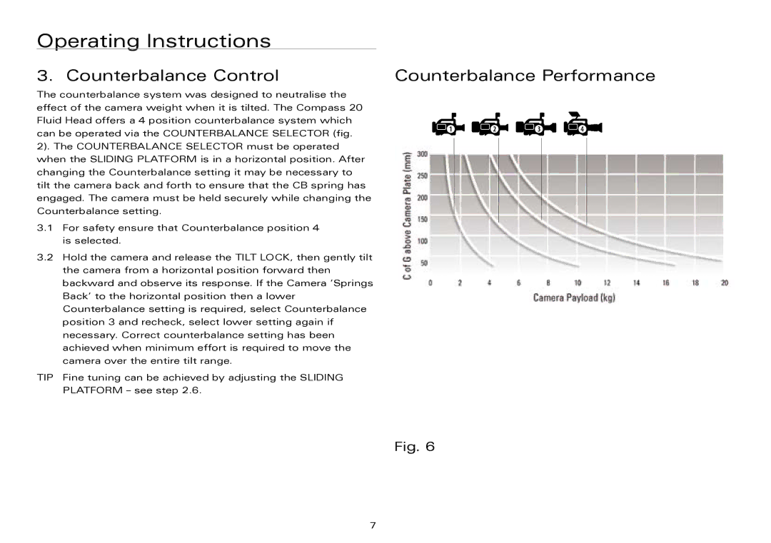
The counterbalance system was designed to neutralise the effect of the camera weight when it is tilted. The Compass 20 Fluid Head offers a 4 position counterbalance system which can be operated via the COUNTERBALANCE SELECTOR (fig.
2). The COUNTERBALANCE SELECTOR must be operated when the SLIDING PLATFORM is in a horizontal position. After changing the Counterbalance setting it may be necessary to tilt the camera back and forth to ensure that the CB spring has engaged. The camera must be held securely while changing the Counterbalance setting.
3.1For safety ensure that Counterbalance position 4 is selected.
3.2Hold the camera and release the TILT LOCK, then gently tilt the camera from a horizontal position forward then backward and observe its response. If the Camera ‘Springs Back’ to the horizontal position then a lower Counterbalance setting is required, select Counterbalance position 3 and recheck, select lower setting again if necessary. Correct counterbalance setting has been achieved when minimum effort is required to move the camera over the entire tilt range.
TIP Fine tuning can be achieved by adjusting the SLIDING
PLATFORM – see step 2.6.
Fig. 6
7