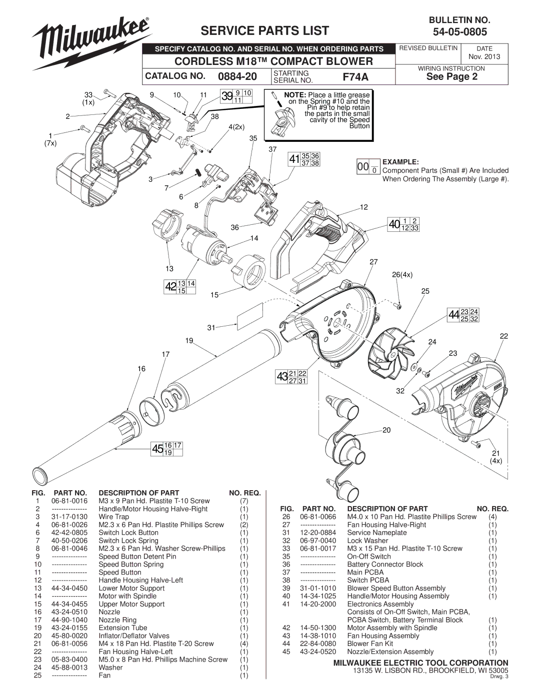
SERVICE PARTS LIST
BULLETIN NO.
54-05-0805
|
| SPECIFY CATALOG NO. AND SERIAL NO. WHEN ORDERING PARTS REVISED BULLETIN | DATE | |||||
|
| CORDLESS M18™ COMPACT BLOWER |
| Nov. 2013 | ||||
|
| WIRING INSTRUCTION | ||||||
| CATALOG NO. |
| STARTING | F74A | ||||
| See Page 2 | |||||||
| SERIAL NO. | |||||||
33 | 9 | 10 | 11 | 9 10 | NOTE: Place a little grease |
|
| |
(1x) |
|
|
| 39 11 | on the Spring #10 and the |
|
| |
|
|
|
|
| Pin #9 to help retain |
|
| |
2 |
|
|
| 38 | the parts in the small |
|
| |
|
|
| cavity of the Speed |
|
| |||
1 |
|
|
| 4(2x) |
| Button |
|
|
|
|
| 35 |
|
|
|
| |
(7x) |
|
|
|
| 37 |
|
|
|
|
|
|
|
|
|
|
| |
|
|
|
|
| 35 36 |
| EXAMPLE: |
|
|
|
|
|
| 41 37 38 | 00 0 |
| |
|
|
|
|
|
| Component Parts (Small #) Are Included | ||
| 3 |
|
|
|
|
| When Ordering The Assembly (Large #). | |
7
6
8
36![]()
14
13
42 1315 14 15![]()
![]()
![]()
31![]()
![]()
12
40 1 2
12 33
27
26(4x)
25
44 23 24
25 32
19
24
22
17
16
23
43 | 21 | 22 |
27 | 31 |
32
20
45 1619 17
21
(4x)
FIG. | PART NO. | DESCRIPTION OF PART | NO. REQ. |
1 | M3 x 9 Pan Hd. Plastite | (7) | |
2 | Handle/Motor Housing | (1) | |
3 | Wire Trap | (1) | |
4 | M2.3 x 6 Pan Hd. Plastite Phillips Screw | (2) | |
6 | Switch Lock Button | (1) | |
7 | Switch Lock Spring | (1) | |
8 | M2.3 x 6 Pan Hd. Washer | (1) | |
9 | Speed Button Detent Pin | (1) | |
10 | Speed Button Spring | (1) | |
11 | Speed Button | (1) | |
12 | Handle Housing | (1) | |
13 | Lower Motor Support | (1) | |
14 | Motor with Spindle | (1) | |
15 | Upper Motor Support | (1) | |
16 | Nozzle | (1) | |
17 | Nozzle Ring | (1) | |
19 | Extension Tube | (1) | |
20 | Inflator/Deflator Valves | (1) | |
21 | M4 x 18 Pan Hd. Plastite | (4) | |
22 | Fan Housing | (1) | |
23 | M5.0 x 8 Pan Hd. Phillips Machine Screw | (1) | |
24 | Washer | (1) | |
25 | Fan | (1) |
FIG. | PART NO. | DESCRIPTION OF PART | NO. REQ. |
26 | M4.0 x 10 Pan Hd. Plastite Phillips Screw | (4) | |
27 | Fan Housing | (1) | |
31 | Service Nameplate | (1) | |
32 | Lock Washer | (1) | |
33 | M3 x 15 Pan Hd. Plastite | (1) | |
35 | (1) | ||
36 | Battery Connector Block | (1) | |
37 | Main PCBA | (1) | |
38 | Switch PCBA | (1) | |
39 | Blower Speed Button Assembly | (1) | |
40 | Handle/Motor Housing Assembly | (1) | |
41 | Electronics Assembly |
| |
|
| Consists of |
|
|
| PCBA Switch, Battery Terminal Block | (1) |
42 | Motor Assembly with Spindle | (1) | |
43 | Fan Housing Assembly | (1) | |
44 | Blower Fan Kit | (1) | |
45 | Nozzle/Extension Assembly | (1) |
MILWAUKEE ELECTRIC TOOL CORPORATION 13135 W. LISBON RD., BROOKFIELD, WI 53005 Drwg. 3
