OPERATION
Selecting Speed
The speed selector is on top of the motor housing.
Starting, Stopping and Controlling Speed
1. To start the tool, grasp the handle firmly and pull |
WARNING Always remove battery pack before changing or removing ac- cessories. Only use accessories specifically recommended for this tool. Others may be
hazardous.
WARNING To reduce the risk of injury, wear safety goggles or glasses with side
shields.
Fuel Gauge
To determine the amount of charge left in the bat- tery, pull the trigger. The Fuel Gauge will light up for
To signal the end of charge, 1 light on the fuel gauge will flash for
Installing Bits
Always remove the battery before inserting or removing bits. Select the proper style and size bit for the job.
This tool is equipped with a spindle lock. The chuck can be tightened with one hand, creating higher grip strengths on the bit.
1.To open the chuck jaws, turn the sleeve in the counterclockwise direction.
When using drill bits, allow the bit to strike the bottom of the chuck. Center the bit in the chuck jaws and lift it about 1/16” off of the bottom.
When using screwdriver bits, insert the bit far enough for the chuck jaws to grip the hex of the bit.
2.To close the chuck jaws, turn the sleeve in the clockwise direction. The bit is secure when the chuck makes a ratcheting sound and the sleeve can not be rotated any further.
3.To remove the bit, turn the sleeve in the coun- terclockwise direction.
NOTE: A ratcheting sound may be heard when the chuck is opened or closed. This noise is part of the locking feature, and does not indicate a problem with the chuck’s operation.
Selecting Drill or Drive Action (Cat. No. 2410-20)
1.To use the drilling mode, rotate the clutch adjusting ring until the
drill symbol ![]() appears in line
appears in line
with the arrow.
2.To use the driving mode rotate 


the clutch adjusting ring until the ![]()
![]()
![]() 2
2 ![]() desired clutch setting appears in
desired clutch setting appears in ![]()
![]()
![]()
![]()
![]()
![]()
![]()
![]()
![]()
![]()
![]()
line with the arrow.![]()
![]()
![]()
![]()
![]()
![]()
![]()
![]()
![]()
![]()
![]()
![]() The adjustable clutch, when prop-
The adjustable clutch, when prop-
erly adjusted, will slip at a preset torque to prevent driving the screw ![]() too deep into different materials
too deep into different materials ![]()
![]()
![]()
![]()
![]()
![]()
![]()
![]()
![]()
![]()
![]()
![]()
![]()
![]() and to prevent damage to the
and to prevent damage to the ![]()
![]()
![]()
![]()
![]()
![]()
![]()
![]() screw or tool.
screw or tool.![]()
![]()
![]()
![]()
![]()
![]()
![]()
![]()
![]()
![]()
![]()
Selecting Hammer, Drill or Drive Action (Cat. No.
1.To use the
selector ring until the hammer | |
symbol | appears in line with |
the arrow. Apply pressure to the | |
bit to engage the hammering | |
mechanism. |
|
NOTE: The number selected on the clutch | |
adjusting ring has no effect on operation of the drill in hammer mode.
NOTE: When using carbide bits, do not use wa- ter to settle dust. Do not attempt to drill through steel reinforcing rods. This will damage the carbide bits.
2.To use the drilling only mode, rotate the application selector ring
until the drill symbol | appears |
in line with the arrow. |
|
NOTE: The number selected on ![]()
![]()
![]()
![]()
![]()
![]()
![]()
![]()
![]()
![]()
![]()
![]()
![]()
![]()
![]()
![]()
![]()
![]() the clutch adjusting ring has no
the clutch adjusting ring has no ![]()
![]() effect on operation of the drill in
effect on operation of the drill in ![]()
![]() drilling mode.
drilling mode.![]()
3.To use the driving screws mode rotate the application selector ring until the drive symbol ![]()
![]()
![]()
![]()
![]() appears
appears
in line with the arrow. Then rotate ![]()
![]()
![]()
![]()
![]()
![]()
![]()
![]()
![]()
![]()
![]()
![]()
![]()
![]()
![]()
![]()
![]()
![]()
![]()
![]()
![]()
![]()
![]()
![]()
![]()
![]() the clutch adjusting ring until the
the clutch adjusting ring until the ![]() desired clutch setting appears in
desired clutch setting appears in ![]()
![]()
![]()
![]()
![]()
![]()
![]()
![]()
![]()
![]()
![]() line with the arrow.
line with the arrow.![]()
![]()
![]() The adjustable clutch, when properly adjusted, will slip at a preset torque to prevent driving the screw too deep into different materials and to prevent damage to the screw or tool.
The adjustable clutch, when properly adjusted, will slip at a preset torque to prevent driving the screw too deep into different materials and to prevent damage to the screw or tool.
The torque specifications shown here are approximate values obtained with a fully charged battery pack.
Torque Specifications for Cat. No.
Clutch |
| Applications | |
Setting | in. lbs | ||
| |||
Small screws in softwood. | |||
Medium screws in softwood or small | |||
screws in hardwood. | |||
Large screws in softwoods. Medium | |||
screws in hardwood or large screws in | |||
|
| hardwood with pilot hole. |
NOTE: Because the settings shown in the table are only a guide, use a piece of scrap material to test the different clutch settings before driving screws into the workpiece.
Allow the tool to come to a complete stop before changing speeds. See “Applications” for recom- mended speeds under various conditions.
1.For Low speed (up to 400 RPM), push the speed selector to display “1”.
2.For High speed (up to 1500 RPM), push the speed selector to display “2”.
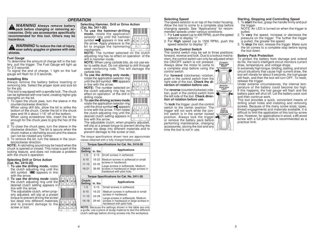
Using the Control Switch
The control switch may be set to three positions: forward, reverse and lock. Due to a lockout mecha- nism, the control switch can only be adjusted when
the ON/OFF switch is not pressed. | Forward - |
Always allow the motor to come to | Push from |
RIGHT | |
a complete stop before using the |
|
control switch. |
|
For forward (clockwise) rotation, |
|
push in the control switch from the |
|
right side of the tool. Check the di- |
|
rection of rotation before use. | Reverse - |
For reverse (counterclockwise) rota- | Push from |
LEFT | |
tion, push in the control switch from |
|
the left side of the tool. Check direc- |
|
tion of rotation before use. |
|
To lock the trigger, push the control |
|
switch to the center position. The | Lock - |
trigger will not work while the con- | Push to |
trol switch is in the center locked | CENTER |
position. Always lock the trigger |
|
or remove the battery pack before |
|
performing maintenance, changing |
|
accessories, storing the tool and any |
|
time the tool is not in use. |
|
| the trigger. |
| NOTE: An LED is turned on when the trigger is |
2. | pulled. |
To vary the speed, increase or decrease the | |
| pressure on the trigger. The further the trigger |
3. | is pulled, the greater the speed. |
To stop the tool, release the trigger. Make sure | |
| the bit comes to a complete stop before laying |
| the tool down. |
Battery Pack Protection
To protect the battery from damage and extend its life, the tool’s intelligent circuit monitors current draw, temperature, and voltage drops.
In extremely high torque, binding, stalling, and short circuit situations that cause high current draw, the tool will vibrate for about 5 seconds, the fuel gauge will flash, and then the tool will turn OFF. To reset, release the trigger.
Under extreme circumstances, the internal tem- perature of the battery could become too high. If this happens, the fuel gauge will flash and the battery pack will shut off. Let the battery pack cool and then continue work.
This tool provides a quick, convenient means of drilling small holes and installing and removing screws. Because of the many screw sizes, types, thread engagements and materials available, it is difficult to limit the application of this tool by screw size. However, for applications in wood, a #6 wood screw with a full pilot hole is recommended as a practical limit.
4 | 5 |