WARNING Use only sockets and other accessories specifically designed for use on impact wrenches and drivers. Other sockets and accessories might shatter or break caus- ing injury.
Attaching and Removing Accessories
These tools are intended only for use with acces- sories designed for impact wrenches and drivers. Other sockets could shatter or break, causing injury.
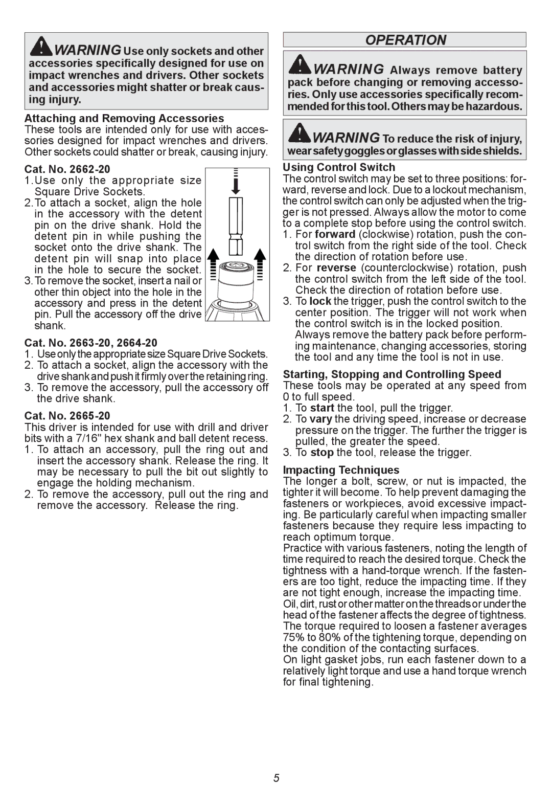
Cat. No. 2662-20  1.Use only the appropriate size
Square Drive Sockets.
2.To attach a socket, align the hole in the accessory with the detent pin on the drive shank. Hold the detent pin in while pushing the socket onto the drive shank. The detent pin will snap into place
in the hole to secure the socket.
3.To remove the socket, insert a nail or
other thin object into the hole in the accessory and press in the detent ![]()
![]()
![]()
![]()
![]()
![]()
![]()
![]()
![]()
![]()
![]()
![]()
![]()
![]() pin. Pull the accessory off the drive
pin. Pull the accessory off the drive ![]()
![]()
![]()
![]()
![]()
![]()
![]()
![]()
![]()
![]()
![]()
![]()
![]()
![]()
![]()
![]()
![]()
![]()
![]()
![]()
![]()
![]() shank.
shank.![]()
![]()
![]()
![]()
![]()
![]()
Cat. No. 2663-20, 2664-20
1. UseonlytheappropriatesizeSquareDriveSockets.
2. To attach a socket, align the accessory with the driveshankandpushitfirmlyovertheretainingring.
3. To remove the accessory, pull the accessory off the drive shank.
Cat. No. 2665-20
This driver is intended for use with drill and driver bits with a 7/16" hex shank and ball detent recess. 1. To attach an accessory, pull the ring out and insert the accessory shank. Release the ring. It may be necessary to pull the bit out slightly to
engage the holding mechanism.
2. To remove the accessory, pull out the ring and remove the accessory. Release the ring.
OPERATION
![]() WARNING Always remove battery pack before changing or removing accesso- ries. Only use accessories specifically recom- mended for this tool. Others may be hazardous.
WARNING Always remove battery pack before changing or removing accesso- ries. Only use accessories specifically recom- mended for this tool. Others may be hazardous.
![]() WARNING To reduce the risk of injury, wearsafetygogglesorglasseswithsideshields.
WARNING To reduce the risk of injury, wearsafetygogglesorglasseswithsideshields.
Using Control Switch
The control switch may be set to three positions: for- ward, reverse and lock. Due to a lockout mechanism, the control switch can only be adjusted when the trig- ger is not pressed. Always allow the motor to come to a complete stop before using the control switch. 1. For forward (clockwise) rotation, push the con-
trol switch from the right side of the tool. Check the direction of rotation before use.
2. For reverse (counterclockwise) rotation, push the control switch from the left side of the tool. Check the direction of rotation before use.
3. To lock the trigger, push the control switch to the center position. The trigger will not work when the control switch is in the locked position.
Always remove the battery pack before perform- ing maintenance, changing accessories, storing the tool and any time the tool is not in use.
Starting, Stopping and Controlling Speed These tools may be operated at any speed from 0 to full speed.
1. To start the tool, pull the trigger.
2. To vary the driving speed, increase or decrease pressure on the trigger. The further the trigger is pulled, the greater the speed.
3. To stop the tool, release the trigger.
Impacting Techniques
The longer a bolt, screw, or nut is impacted, the tighter it will become. To help prevent damaging the fasteners or workpieces, avoid excessive impact- ing. Be particularly careful when impacting smaller fasteners because they require less impacting to reach optimum torque.
Practice with various fasteners, noting the length of time required to reach the desired torque. Check the tightness with a
On light gasket jobs, run each fastener down to a relatively light torque and use a hand torque wrench for final tightening.
5