Chicago |
|
|
|
|
|
|
|
| BULLETIN NO. | ||
PneumaticT M SERVICE PARTS LIST |
|
|
|
|
|
|
| ||||
| SPECIFY CATALOG NO. AND SERIAL NO. WHEN ORDERING PARTS | REVISED BULLETIN | DATE | ||||||||
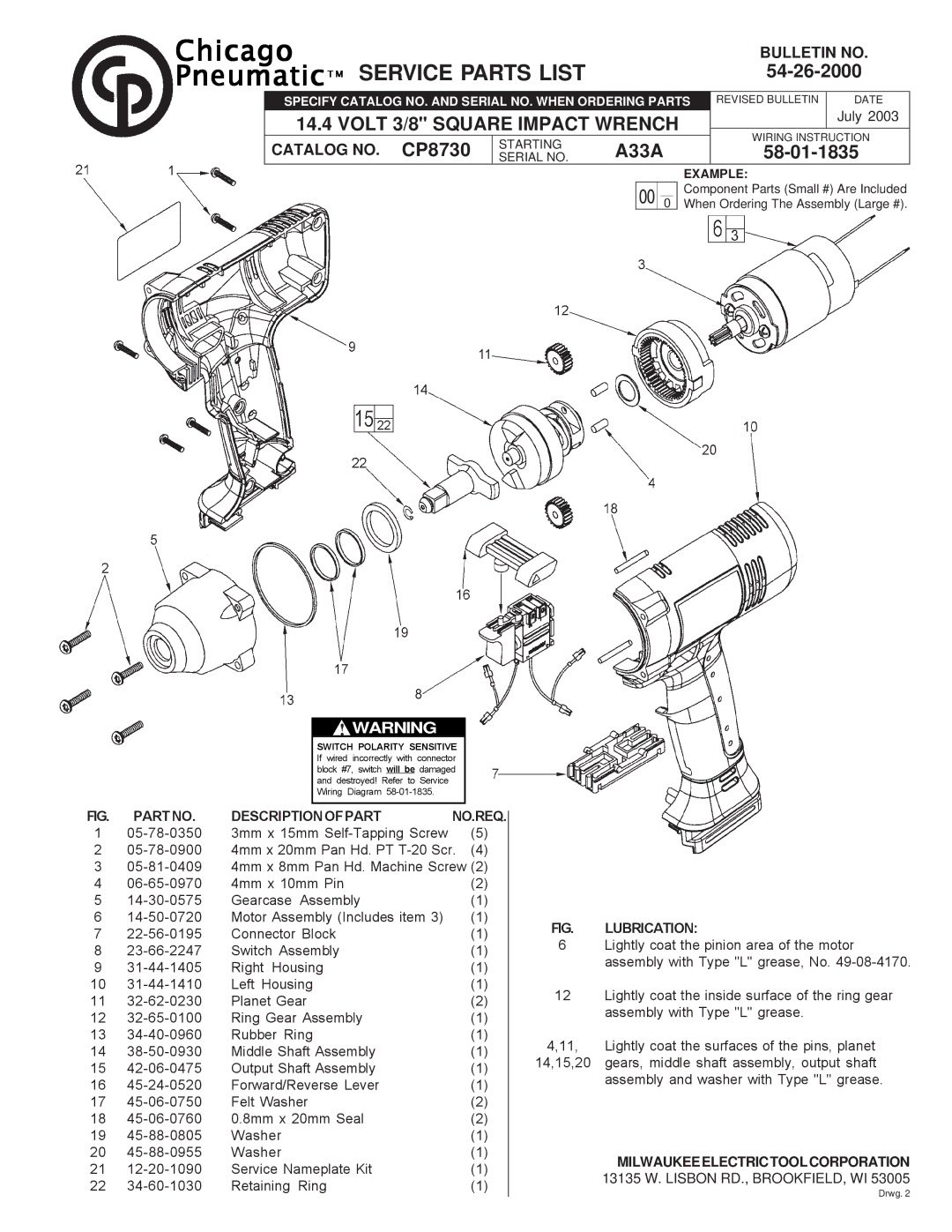
| 14.4 VOLT 3/8" SQUARE IMPACT WRENCH |
|
| July 2003 | |||||||
|
|
|
| ||||||||
| WIRING INSTRUCTION | ||||||||||
| CATALOG NO. CP8730 | STARTING | A33A |
| |||||||
|
|
| |||||||||
| SERIAL NO. |
| |||||||||
|
|
|
|
|
|
|
|
| EXAMPLE: | ||
|
|
|
| 00 |
|
|
|
| Component Parts (Small #) Are Included | ||
|
|
|
|
| 0 |
|
| When Ordering The Assembly (Large #). | |||
!WARNING
SWITCH POLARITY SENSITIVE If wired incorrectly with connector block #7, switch will be damaged and destroyed! Refer to Service Wiring Diagram
FIG. PARTNO. DESCRIPTIONOFPART NO.REQ.
1
2
3
4 | 4mm x 10mm Pin | (2) | |
5 | Gearcase Assembly | (1) | |
6 | Motor Assembly (Includes item 3) | (1) | |
7 | Connector Block | (1) | |
8 | Switch Assembly | (1) | |
9 | Right Housing | (1) | |
10 | Left Housing | (1) | |
11 | Planet Gear | (2) | |
12 | Ring Gear Assembly | (1) | |
13 | Rubber Ring | (1) | |
14 | Middle Shaft Assembly | (1) | |
15 | Output Shaft Assembly | (1) | |
16 | Forward/Reverse Lever | (1) | |
17 | Felt Washer | (2) | |
18 | 0.8mm x 20mm Seal | (2) | |
19 | Washer | (1) | |
20 | Washer | (1) | |
21 | Service Nameplate Kit | (1) | |
22 | Retaining Ring | (1) |
FIG. LUBRICATION:
6Lightly coat the pinion area of the motor assembly with Type "L" grease, No.
12Lightly coat the inside surface of the ring gear assembly with Type "L" grease.
4,11, Lightly coat the surfaces of the pins, planet 14,15,20 gears, middle shaft assembly, output shaft assembly and washer with Type "L" grease.
MILWAUKEEELECTRICTOOLCORPORATION
13135 W. LISBON RD., BROOKFIELD, WI 53005
Drwg. 2