SPECIFICATIONS
Charger
Cat. No.
AC Input
Volts
AC Input
Amps
1.15
DC Output
Volts
12 or 18V
DC Output |
| Battery Cat. No. | DC Volts |
Amps |
| M18B | 18 |
3 |
| M18BX | 18 |
|
| M12B | 12 |
|
| M12BX | 12 |
SYMBOLOGY
FUNCTIONAL DESCRIPTION
Volts Direct Current
Volts Alternating Current
Double Insulated
Hertz
6
5
8
7
6
1
2
5
2
1
4 ![]()
![]()
![]()
![]()
![]()
![]()
![]()
![]()
![]()
![]()
![]() 3
3 ![]()
![]()
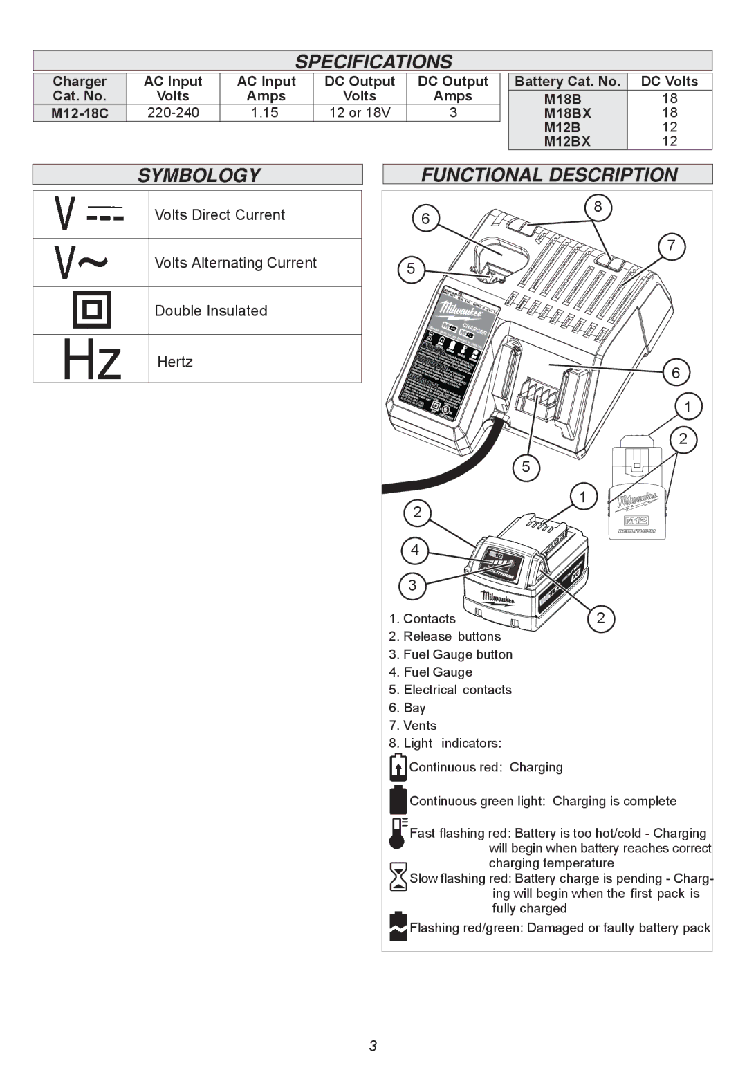
1. Contacts | 2 |
2.Release buttons
3.Fuel Gauge button
4.Fuel Gauge
5.Electrical contacts
6.Bay
7.Vents
8.Light indicators:
Continuous red: Charging
Continuous green light: Charging is complete
Fast flashing red: Battery is too hot/cold - Charging will begin when battery reaches correct charging temperature
![]() Slow flashing red: Battery charge is pending - Charg-
Slow flashing red: Battery charge is pending - Charg-
ing will begin when the first pack is fully charged
Flashing red/green: Damaged or faulty battery pack
3