A. LineGuard CAT 5 Modules (Models:
MMS-CAT5-LAN-RJ45, MMS-CAT5-POE-
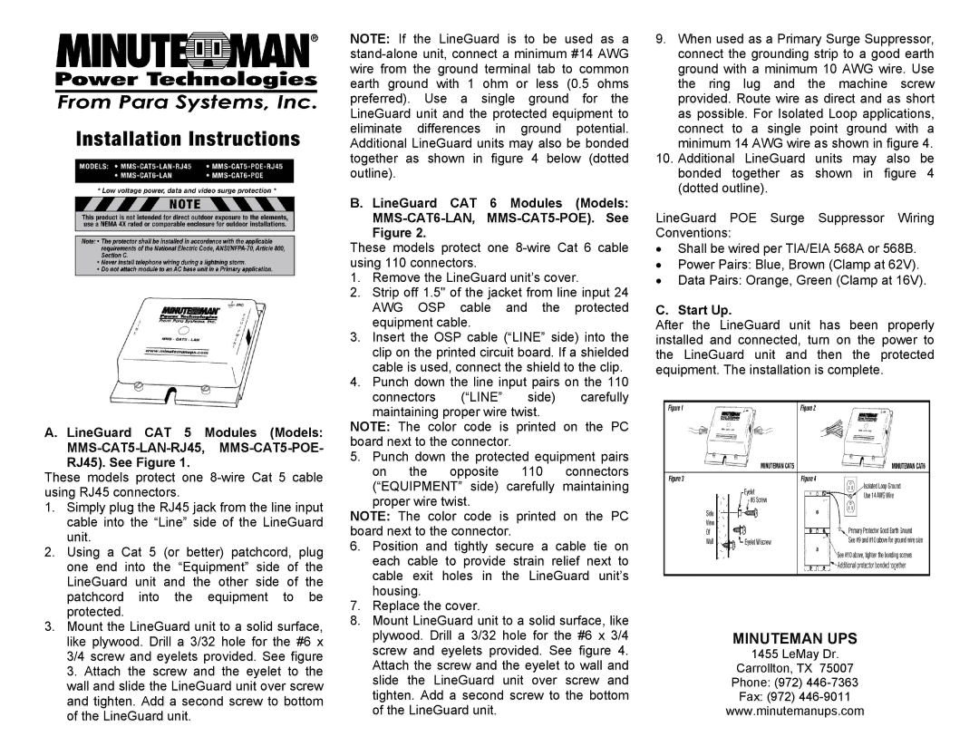
RJ45). See Figure 1.
These models protect one
1.Simply plug the RJ45 jack from the line input cable into the “Line” side of the LineGuard unit.
2.Using a Cat 5 (or better) patchcord, plug one end into the “Equipment” side of the LineGuard unit and the other side of the patchcord into the equipment to be protected.
3.Mount the LineGuard unit to a solid surface, like plywood. Drill a 3/32 hole for the #6 x 3/4 screw and eyelets provided. See figure 3. Attach the screw and the eyelet to the wall and slide the LineGuard unit over screw and tighten. Add a second screw to bottom of the LineGuard unit.
NOTE: If the LineGuard is to be used as a
B. LineGuard CAT 6 Modules (Models:
Figure 2.
These models protect one
1.Remove the LineGuard unit’s cover.
2.Strip off 1.5" of the jacket from line input 24 AWG OSP cable and the protected equipment cable.
3.Insert the OSP cable (“LINE” side) into the clip on the printed circuit board. If a shielded cable is used, connect the shield to the clip.
4.Punch down the line input pairs on the 110 connectors (“LINE” side) carefully
maintaining proper wire twist.
NOTE: The color code is printed on the PC board next to the connector.
5.Punch down the protected equipment pairs on the opposite 110 connectors
(“EQUIPMENT” side) carefully maintaining proper wire twist.
NOTE: The color code is printed on the PC board next to the connector.
6.Position and tightly secure a cable tie on each cable to provide strain relief next to cable exit holes in the LineGuard unit’s housing.
7.Replace the cover.
8.Mount LineGuard unit to a solid surface, like plywood. Drill a 3/32 hole for the #6 x 3/4 screw and eyelets provided. See figure 4. Attach the screw and the eyelet to wall and slide the LineGuard unit over screw and tighten. Add a second screw to the bottom of the LineGuard unit.
9.When used as a Primary Surge Suppressor, connect the grounding strip to a good earth ground with a minimum 10 AWG wire. Use the ring lug and the machine screw provided. Route wire as direct and as short as possible. For Isolated Loop applications, connect to a single point ground with a minimum 14 AWG wire as shown in figure 4.
10.Additional LineGuard units may also be bonded together as shown in figure 4 (dotted outline).
LineGuard POE Surge Suppressor Wiring Conventions:
•Shall be wired per TIA/EIA 568A or 568B.
•Power Pairs: Blue, Brown (Clamp at 62V).
•Data Pairs: Orange, Green (Clamp at 16V).
C. Start Up.
After the LineGuard unit has been properly installed and connected, turn on the power to the LineGuard unit and then the protected equipment. The installation is complete.
MINUTEMAN UPS
1455 LeMay Dr.
Carrollton, TX 75007 Phone: (972)