6

Dip S/W setting for outdoor units and indoor units

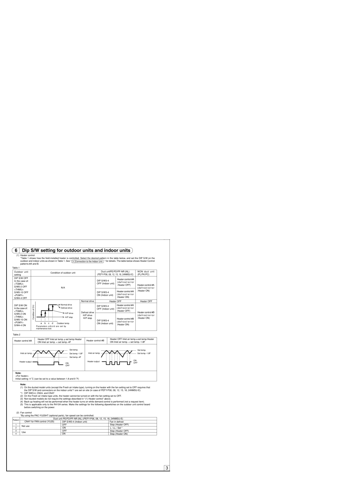
(1)Heater control

*Table 1 shows how the field-installed heater is controlled. Select the desired pattern in the table below, and set the DIP S/W on the

outdoor and indoor units as shown in Table 1. See “ 3 Connection to the Indoor Unit ” for details. The table below shows Heater Control patterns #A and B.

Table.1

Outdoor unit


Condition of outdoor unit


Duct unitPE/PD/PF-NR (NL)


NON duct unit

setting


(PEFY-P06, 08, 12, 15, 18, 24NMSU-E)


(PL/PK/PC)


DIP S/W OFF


DIP S/W3-4


Heater control #A


In the case of:


( d e f r o s t / e r r o r


<TGMU>


OFF (Indoor unit)


:Heater OFF)


Heater control #A

S/W5-2 OFF


N/A


( d e f r o s t / e r r o r

<THMU>


Heater control #A


:Heater ON)

S/W5-10 OFF


DIP S/W3-4


( d e f r o s t / e r r o r


<PUMY>


ON (Indoor unit)


:Heater ON)


S/W4-4 OFF


Normal drive


Heater OFF


Heater OFF

DIP S/W ON


O/U


Normal drive


DIP S/W3-4


Heater control #A


In the case of:


Defrost drive


( d e f r o s t / e r r o r


of


OFF (Indoor unit)


<TGMU>


:Heater OFF)


Condition


H/P stop


:Heater ON)


Heater control #B


S/W5-2 ON


H/P drive


Defrost drive


Heater control #B

<THMU>


H/P stop


H/P drive


( d e f r o s t / e r r o r


S/W5-10 ON


DIP S/W3-4


( d e f r o s t / e r r o r


<PUMY>


a b c d

Outdoor temp.


ON (Indoor unit)


:Heater ON)


S/W4-4 ON


Parameters a/b/c/d are set by


maintenance tool.


Table.2


Heater control #A


Heater OFF Inlet air temp.


set temp.Heater


Heater control #B


Heater OFF Inlet air temp.


set temp.Heater


ON Inlet air temp. < set temp.-4F


ON Inlet air temp. < set temp.-1.8F


Set temp.


Set temp.

Inlet air temp.


Set temp.-1.8F


Inlet air temp.


Set temp.-1.8F


Set temp.-4F


Heater output


Heater output


ON


ON


OFF


OFF


Note:

<For heater>

Initial setting: 4 ˚C (can be set to a value between 1.8 and 9 ˚F)


Note:


(1)

On the ducted model units (except the Fresh air intake type), turning on the heater with the fan setting set to OFF requires that


the DIP S/W and connectors on the indoor units*1 are set on site (in case of PEFY-P06, 08, 12, 15, 18, 24NMSU-E).


*1: DIP SW3-4, CN24, and CN4Y


(2)

On the Fresh air intake type units, the heater cannot be turned on with the fan setting set to OFF.


(3)

Non-ducted models do not require the settings described in “(1) Heater control” above.


(4)

Back-up heating will not be performed when the heater turns on while demand control is performed (not a request item).


(5)

This is applicable only to the R410A series. Make the settings for the following dipswitches on the outdoor unit control board


before switching on the power.


(2) Fan control


*By using the PAC-YU25HT (optional parts), fan speed can be controlled.


Pattern


Duct unit PE/PD/PF-NR (NL) (PEFY-P06, 08, 12, 15, 18, 24NMSU-E)


CN4Y for FAN control (YU25)

DIP S/W3-4 (Indoor unit)

Fan in defrost

1

Not use

OFF

Stop (Heater OFF)

2

ON

L / LL / Set *


3

Use

OFF

Stop (Heater OFF)

4

ON

Stop (Heater ON)


3

Page 3
Image 3
Mitsubishi Electronics PAC-YU25HT installation manual Dip S/W setting for outdoor units and indoor units

PAC-YU25HT specifications

Mitsubishi Electronics has long been a leader in the field of climate control technologies, and the PAC-YU25HT is a testament to their commitment to innovation and efficiency. Designed primarily for use in commercial and industrial applications, this advanced air conditioning unit offers a range of features that ensure optimal performance and reliability.

At the heart of the PAC-YU25HT is its powerful inverter technology, which allows for variable speed operation. This means that the unit can adjust its cooling output according to the needs of the environment. By efficiently modulating the compressor speed, the PAC-YU25HT not only provides optimal temperature control but also minimizes energy consumption, making it an environmentally friendly choice.

One of the standout features of the PAC-YU25HT is its high cooling capacity, making it suitable for larger spaces. With a capacity of 25 kW, it can effectively manage the cooling needs of extensive commercial environments, ensuring comfort for occupants even in the warmest conditions. The unit is also equipped with a sophisticated air filtration system. This system effectively captures dust, pollen, and other allergens, improving indoor air quality and creating a healthier environment.

The PAC-YU25HT is designed with user convenience in mind. Its intuitive control interface allows for easy operation and monitoring, providing users with the flexibility to set their preferred cooling schedules. Moreover, the unit is compatible with a range of smart building technologies, enabling it to be integrated into existing building management systems for enhanced functionality.

Robust and durable, the PAC-YU25HT is built to withstand harsh environmental conditions. Its high-quality materials and construction ensure longevity and reliability, making it a worthwhile investment for businesses looking to enhance their climate control systems.

In addition, Mitsubishi's commitment to innovation is evident in the PAC-YU25HT's low noise operation. The unit is designed to operate quietly, making it ideal for environments where noise reduction is crucial, such as offices or conference rooms.

In summary, the Mitsubishi Electronics PAC-YU25HT combines high capacity, energy efficiency, and advanced technology, making it an exceptional choice for commercial and industrial cooling solutions. With its user-friendly features and robust design, it continues to set the standard for modern air conditioning systems.