Manuals
/
Mitsubishi Electronics
/
Computer Equipment
/
Network Card
Mitsubishi Electronics
QJ71E71-100, QJ71E71-B5, QJ71E71-B2
manual
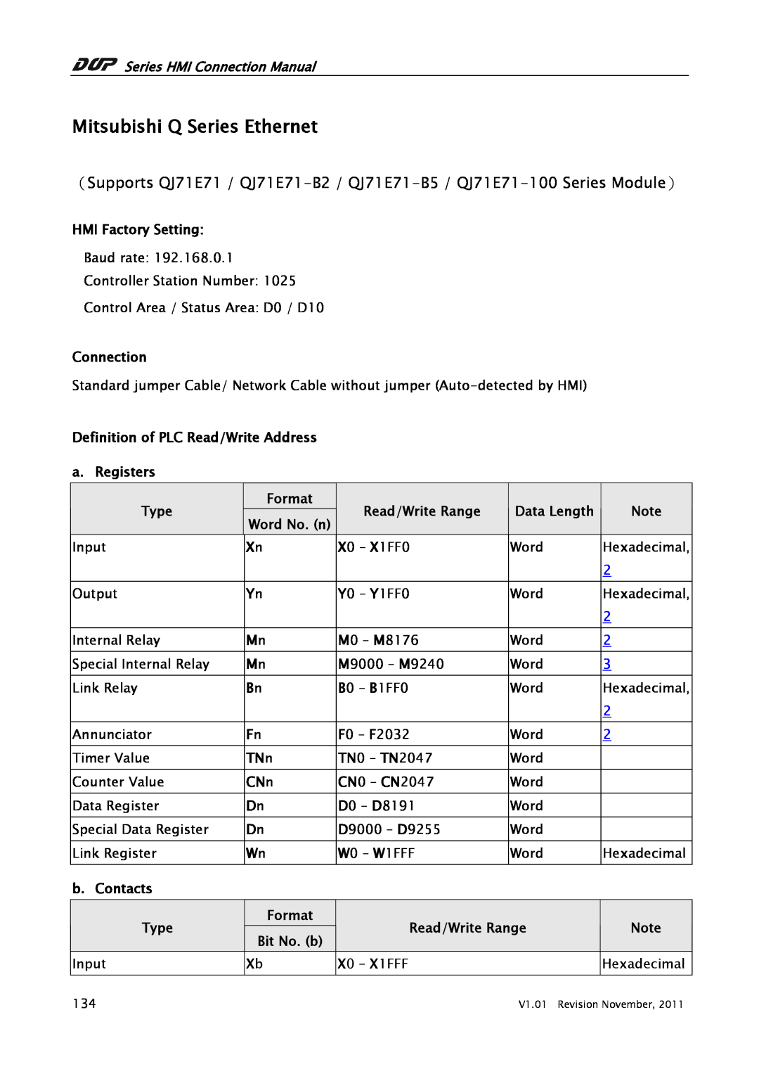
Mitsubishi Q Series Ethernet
Models:
QJ71E71
QJ71E71-B2
QJ71E71-100
QJ71E71-B5
1
1
5
5
Download
5 pages
25.16 Kb
1
2
3
4
5
Settings
Page 1
Image 1
Page 1
Page 2
Page 1
Image 1
Page 1
Page 2
Contents
Series HMI Connection Manual
Mitsubishi Q Series Ethernet
Type
Screen Editor 1. HMI Configuration Setting
Settings
2. PLC Configuration Setting GX Developer V8.35M
Operation Settings
Top
Page
Image
Contents