Installation - In-Wall Units
The CP Series
CORRECTLY PLEASE CONTACT YOUR LOCAL AUTHORISED MONITOR AUDIO DEALER OR CUSTOM INSTALLER.
Parts List
PLEASE CHECK YOU HAVE THE FOLLOWING ITEMS IN THIS KIT BEFORE PROCEEDING:
∙1 x Complete speaker & tweeter assembly fitted to back box.
∙1 x Grille (which can be painted).
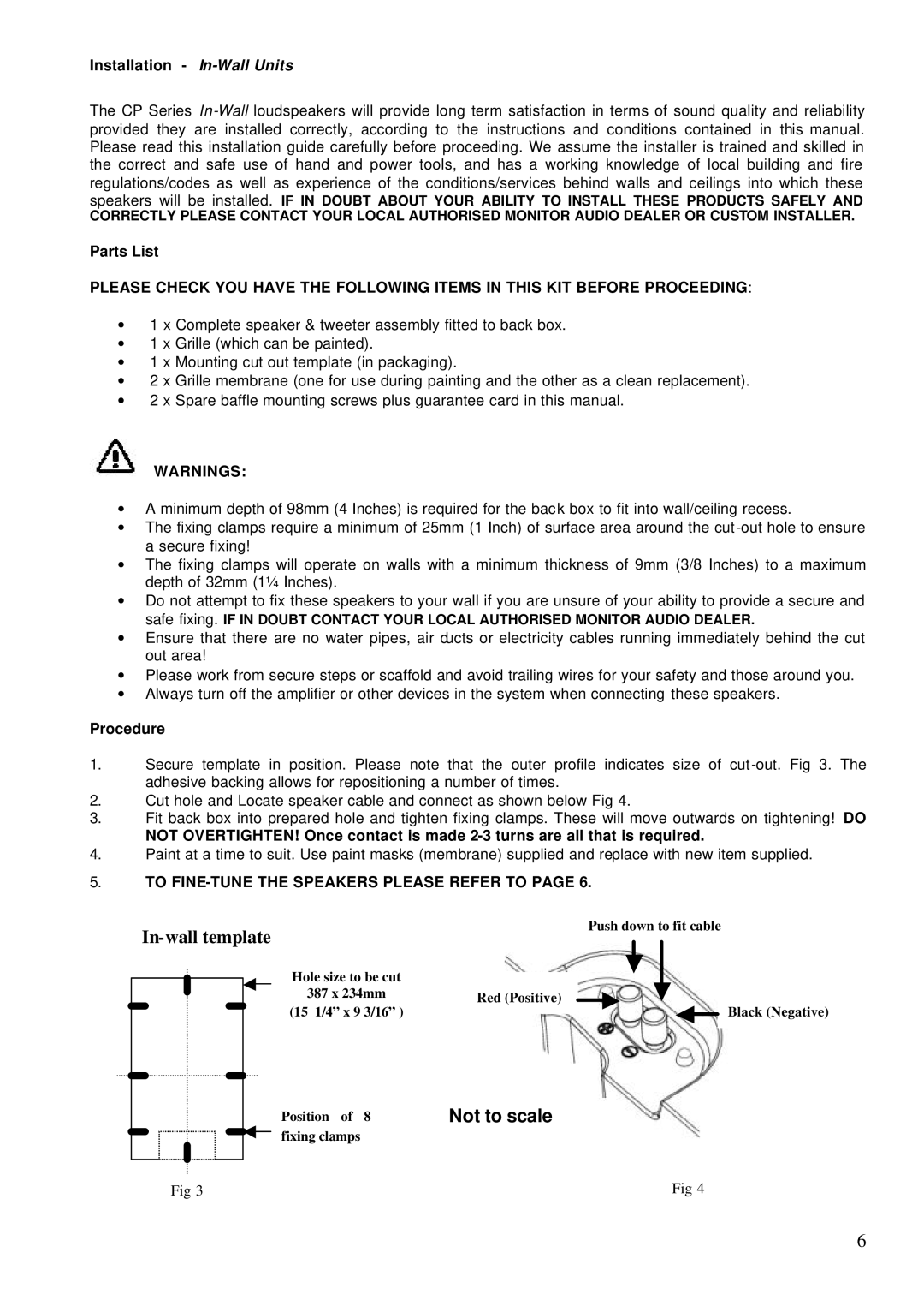
∙1 x Mounting cut out template (in packaging).
∙2 x Grille membrane (one for use during painting and the other as a clean replacement).
∙2 x Spare baffle mounting screws plus guarantee card in this manual.
WARNINGS:
∙A minimum depth of 98mm (4 Inches) is required for the back box to fit into wall/ceiling recess.
∙The fixing clamps require a minimum of 25mm (1 Inch) of surface area around the
∙The fixing clamps will operate on walls with a minimum thickness of 9mm (3/8 Inches) to a maximum depth of 32mm (1¼ Inches).
∙Do not attempt to fix these speakers to your wall if you are unsure of your ability to provide a secure and safe fixing. IF IN DOUBT CONTACT YOUR LOCAL AUTHORISED MONITOR AUDIO DEALER.
∙Ensure that there are no water pipes, air ducts or electricity cables running immediately behind the cut out area!
∙Please work from secure steps or scaffold and avoid trailing wires for your safety and those around you.
∙Always turn off the amplifier or other devices in the system when connecting these speakers.
Procedure
1.Secure template in position. Please note that the outer profile indicates size of
2.Cut hole and Locate speaker cable and connect as shown below Fig 4.
3.Fit back box into prepared hole and tighten fixing clamps. These will move outwards on tightening! DO
NOT OVERTIGHTEN! Once contact is made
4.Paint at a time to suit. Use paint masks (membrane) supplied and replace with new item supplied.
5.TO FINE-TUNE THE SPEAKERS PLEASE REFER TO PAGE 6.
|
|
| Push down to fit cable |
| ||||||||||||
|
|
|
|
|
|
|
|
| ||||||||
|
|
|
|
|
|
|
|
| ||||||||
|
|
|
|
|
|
| Hole size to be cut |
|
|
|
|
|
|
|
|
|
|
|
|
|
|
|
|
|
|
|
|
|
|
|
|
| |
|
|
|
|
|
|
|
|
|
|
|
|
|
|
|
| |
|
|
|
|
|
|
| 387 x 234mm | Red (Positive) |
|
|
|
|
|
|
|
|
|
|
|
|
|
|
|
|
|
|
|
|
|
|
| ||
|
|
|
|
|
|
| (15 1/4” x 9 3/16” ) |
|
|
|
|
|
|
| Black (Negative) | |
|
|
|
|
|
|
|
|
|
|
|
|
|
| |||
|
|
|
|
|
|
|
|
|
|
|
|
|
| |||
|
|
|
|
|
|
|
|
|
|
|
|
|
|
|
|
|
Position of 8 fixing clamps
Not to scale
Fig 3 | Fig 4 |
6