
5PE56 specifications
Monte Carlo Fan Company has established itself as a prominent name in the world of ceiling fans, known for blending style, performance, and energy efficiency. One of its standout models is the Monte Carlo Fan Company 5PE56, which encapsulates the essence of modern ceiling fan design while delivering exceptional functionality.The 5PE56 model features a contemporary aesthetic that complements a wide range of home decors. Its sleek lines and elegant finish make it a perfect fit for both casual and formal spaces. Available in various colors, homeowners have the flexibility to choose a look that suits their specific style needs, whether it be a bold statement piece or a subtle accent.
One of the main features of the Monte Carlo 5PE56 is its powerful motor. Engineered for optimal airflow, it provides impressive performance even in larger spaces. The motor is not only efficient but also remarkably quiet, allowing for serene indoor environments. This quality is particularly valued in areas where noise can be disruptive, such as bedrooms or offices.
In addition to its robustness, the 5PE56 incorporates innovative technologies like the DC motor. DC motors are known for their energy efficiency, consuming significantly less electricity than standard AC motors. This translates into lower energy bills for consumers without sacrificing performance. The fan also has multiple speed settings, allowing users to customize airflow according to their comfort levels.
The Monte Carlo Fan Company has also prioritized user convenience in the design of the 5PE56. It includes a remote control that allows homeowners to easily adjust speeds and settings from across the room. This feature enhances the overall user experience, making it simple to achieve the desired ambiance in any space.
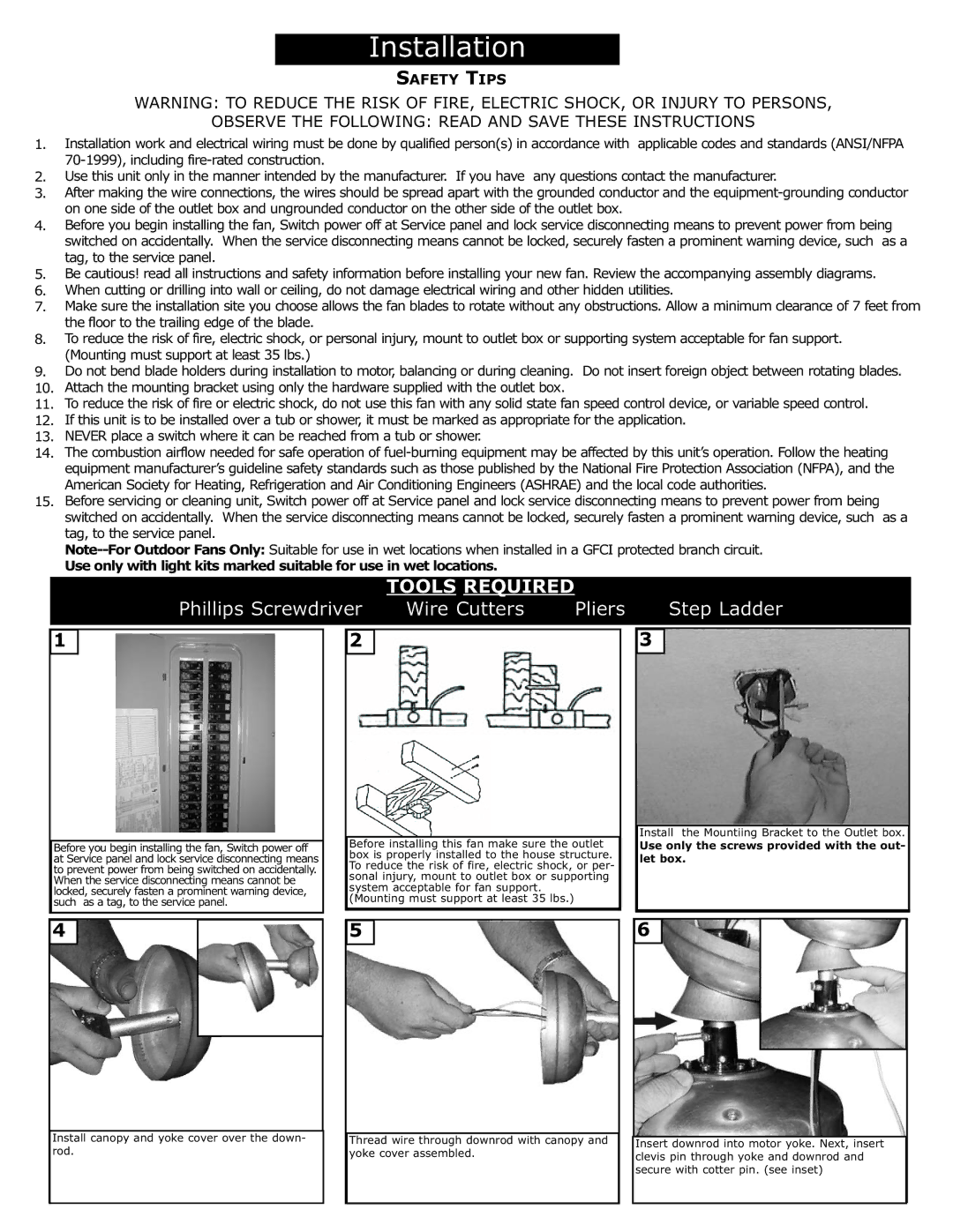
Another noteworthy characteristic of the 5PE56 is its versatility in installation options. It can be mounted on flat ceilings or vaulted ceilings, accommodating a variety of spaces. Furthermore, the fan's size, at 56 inches in diameter, strikes a balance between being large enough to circulate air effectively while remaining sleek and unobtrusive.
Overall, the Monte Carlo Fan Company 5PE56 is a comprehensive solution for those seeking to enhance their indoor environments. With its combination of cutting-edge technology, aesthetic appeal, and user-friendly features, it represents an excellent investment for any home. Whether for comfort, style, or efficiency, the 5PE56 is a testament to Monte Carlo Fan Company's commitment to excellence in ceiling fan design.