Connecting
Data+ | D+ | RS |
|
|
|
|
|
Data- | D- | - |
|
| 485 |
|
|
GND | GND | 485 | Rx | Tx | GND | GND | |
|
|
| Tx | Rx | - | D- | Data- |
|
|
|
|
| RS | D+ | Data+ |
Serial Copper |
| Fiber | Copper Serial | ||||
Device |
|
| Device | ||||
Connecting RS-232 Serial Devices
Wavelength | 1310 nm | |
| 850 nm | |
TX Output | > | |
| > | |
RX Sensitivity | ||
| ||
Half or Full duplex | ||
Half duplex, fiber ring | ||
Environmental |
|
|
Operating Temperature | 0 to 60°C (32 to 142°F), 5 to 95 % RH | |
DTR |
|
| |
DSR |
|
| |
RTS |
|
| |
CTS |
|
| |
PC Rx | Tx | RS- | |
Tx | Rx | ||
232 | |||
GND | GND | ||
|
Copper
6. Switch Settings
|
|
|
| DTR | |
|
|
|
| DSR | |
|
|
|
| RTS | |
|
|
|
| CTS | |
Rx | Tx | 232 | GND | GND | |
Rx | Tx | ||||
|
| - | |||
Tx | Rx | RS | Tx | Rx | |
|
|
| |||
| Fiber | Copper Serial | |||
|
| Device | |||
Extended Operating | |
Temperature (for |
|
Storage Temperature | |
Power |
|
Input Power Voltage | 12 to 48 VDC * |
Power Line Protection | 1 KV Burst (EFT), |
| 1 KV Surge, |
Reverse Power Protection | Protects against V+/V- reversal |
Over Current Protection | Protects against 2 signals shorted together: 1.1A |
Power Consumption | 100 mA at 12 VDC |
Mechanical |
|
Dimensions (W × D × H) | 67 × 100 × 22 mm |
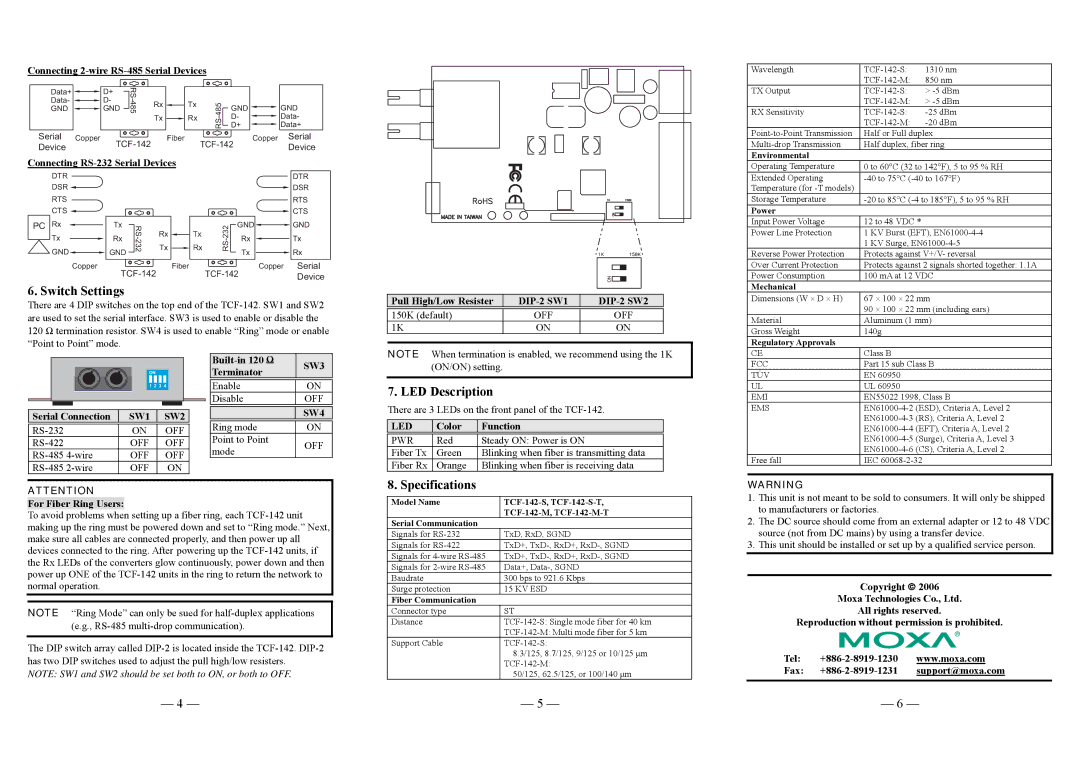
There are 4 DIP switches on the top end of the
|
|
|
|
|
|
|
|
|
|
|
|
| SW3 | |
|
|
|
|
|
|
|
|
|
|
|
|
| ||
|
|
|
|
| ON |
|
|
|
|
| Terminator |
| ||
|
|
|
|
|
|
|
|
|
|
|
|
|
|
|
|
|
|
|
| 1 | 2 | 3 | 4 |
|
|
|
| Enable | ON |
|
|
|
|
|
|
|
|
|
|
|
|
| Disable | OFF |
|
|
|
|
|
|
|
|
|
|
|
|
|
|
|
Serial Connection | SW1 |
| SW2 |
|
|
| SW4 | |||||||
|
|
|
|
| ||||||||||
| ON |
| OFF |
|
| Ring mode | ON | |||||||
|
|
|
| Point to Point |
| |||||||||
OFF |
| OFF |
|
| OFF | |||||||||
OFF |
| OFF |
|
| mode |
| ||||||||
|
|
|
|
| ||||||||||
OFF |
|
| ON |
|
|
|
| |||||||
ATTENTION
For Fiber Ring Users:
To avoid problems when setting up a fiber ring, each
NOTE “Ring Mode” can only be sued for
The DIP switch array called
NOTE: SW1 and SW2 should be set both to ON, or both to OFF.
Pull High/Low Resister | ||
|
|
|
150K (default) | OFF | OFF |
1K | ON | ON |
NOTE When termination is enabled, we recommend using the 1K (ON/ON) setting.
7. LED Description
There are 3 LEDs on the front panel of the
LED | Color | Function |
|
|
|
PWR | Red | Steady ON: Power is ON |
Fiber Tx | Green | Blinking when fiber is transmitting data |
Fiber Rx | Orange | Blinking when fiber is receiving data |
8. Specifications
Model Name | |
| |
Serial Communication |
|
Signals for | TxD, RxD, SGND |
Signals for | TxD+, |
Signals for | TxD+, |
Signals for | Data+, |
Baudrate | 300 bps to 921.6 Kbps |
Surge protection | 15 KV ESD |
Fiber Communication |
|
Connector type | ST |
Distance | |
| |
Support Cable | |
| 8.3/125, 8.7/125, 9/125 or 10/125 μm |
| |
| 50/125, 62.5/125, or 100/140 μm |
| 90 × 100 × 22 mm (including ears) |
Material | Aluminum (1 mm) |
Gross Weight | 140g |
Regulatory Approvals |
|
CE | Class B |
FCC | Part 15 sub Class B |
TÜV | EN 60950 |
UL | UL 60950 |
EMI | EN55022 1998, Class B |
EMS | |
| |
| |
| |
| |
Free fall | IEC |
WARNING
1.This unit is not meant to be sold to consumers. It will only be shipped to manufacturers or factories.
2.The DC source should come from an external adapter or 12 to 48 VDC source (not from DC mains) by using a transfer device.
3.This unit should be installed or set up by a qualified service person.
Copyright © 2006
Moxa Technologies Co., Ltd.
All rights reserved.
Reproduction without permission is prohibited.
Tel:
Fax:
— 4 — | — 5 — | — 6 — |
